
LED module and manufacturing process thereof

A LED module and manufacturing process technology, applied in the direction of electrical components, circuits, semiconductor devices, etc., can solve the problems of low optical transmittance, low light output efficiency, and low heat dissipation performance, and achieve low cost, good heat dissipation effect, and production The effect of simple process

Inactive Publication Date: 2011-02-23
ZHEJIANG XIZI OPTOELECTRONICS TECH
View PDF2 Cites 20 Cited by
  • Summary
  • Abstract
  • Description
  • Claims
  • Application Information

AI Technical Summary

Problems solved by technology

[0008] The first purpose of the present invention is to provide an LED module to solve the technical problems of low heat dissipation performance, low optical transmittance or high cost in the prior art
[0009] The second purpose of the present invention is to provide a LED module manufacturing process to solve the problems of low heat dissipation performance, low light extraction efficiency and high cost in the prior art

Method used


Image

  • LED module and manufacturing process thereof
  • LED module and manufacturing process thereof
  • LED module and manufacturing process thereof

Examples


Embodiment Construction

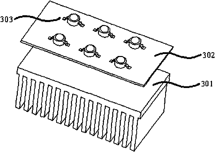
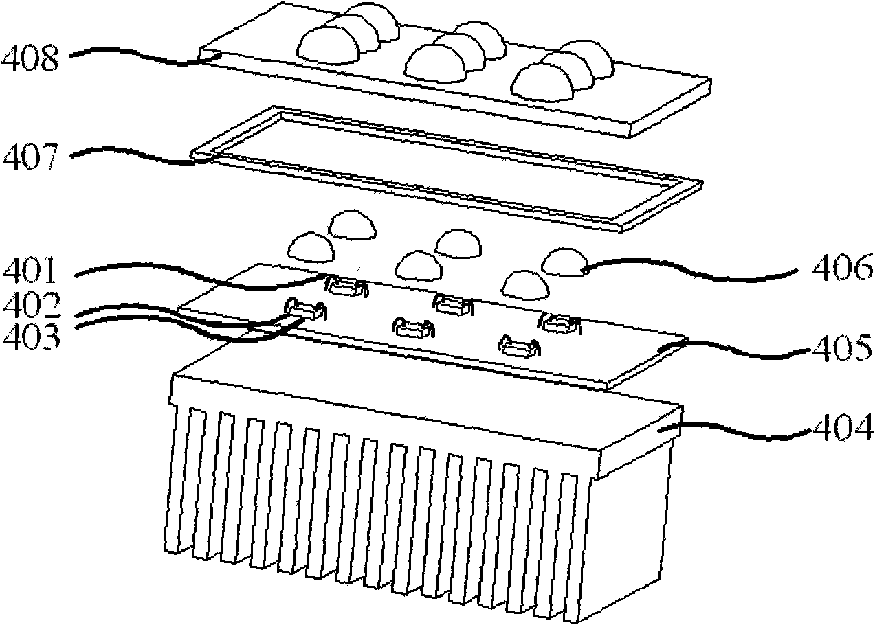
[0041] The core of this application lies in: the existing LED modules usually fix the LED chip on the heat sink of the bracket, package it into LED particles, weld the LED particles on different circuit boards, and then install them on the radiator to form different products , to adapt to more and wider applications, and become a technical bias in the industry, and the structure of this LED module has disadvantages such as poor heat dissipation performance, low optical transmittance, and complicated components. The applicant overcame the existing technical prejudice in the field of LED lighting and its application occasions, and proposed a new LED module structure, in which the LED chip is directly loaded on the circuit board, and the lens module is used for one-time configuration. Light, achieve better heat dissipation effect and higher light extraction efficiency, and solve the packaging problem of LED chips on the circuit board.

[0042] Such as figure 2 As shown, an LED ...


PUM


Abstract

The invention discloses an LED module, which comprises a radiator, a circuit board, an LED chip, an intraconnection track, filling colloid and a lens module, wherein the LED chip is fixed on the circuit board coated with a prime coat; the intraconnection track bridges the LED chip and the pad of the corresponding circuit board; the filling colloid is poured to embed the LED chip and the intraconnection track; the circuit board and the radiator are tightly jointed by faces; and the lens module is covered on the LED chip, the circuit board and the radiator. The LED chip is solidified on the circuit board directly, so the conventional LED packaging process is not used; and a bracket with a heat sink is not used, so that the heat of the LED chip is dissipated to the circuit board and the radiation, which have high heat conductivity, without passing through a heat skink intermediate layer, so the heat dissipation effect is improved. As only the filling colloid is filled between the lens module and the LED chip, light passes through fewer mediums and the transmissivity is high; and the refractive index of the filling colloid and the refractive index of the lens module are matched, so the reflection loss is little and the light rate of the LED module is improved.

Description

technical field [0001] The invention relates to the field of semiconductor application and packaging, and more specifically relates to an LED (light emitting diode) module and a manufacturing process thereof. Background technique [0002] With the development of LED chip technology and packaging technology, more and more LED products are used in the field of lighting, especially high-power white LEDs. Due to the characteristics of high light efficiency, long life, energy saving and environmental protection, suitable dimming control, and no mercury and other pollutants, LEDs have become a new generation of lighting sources after traditional light sources such as incandescent lamps and fluorescent lamps. [0003] LED is an electroluminescent semiconductor device, in which about 30% of the electrical energy is converted into light, and the remaining electrical energy is converted into heat, and the temperature rise of LED caused by heat accumulation is the main cause of LED lig...

Claims


Application Information

Patent Timeline
Patent Type & Authority Applications(China)
IPC IPC(8): H01L33/00H01L33/64H01L33/48
Inventor 陈凯黄建明章子奇
Owner ZHEJIANG XIZI OPTOELECTRONICS TECH
Learn More