Light emitting diode light bulbs with strands of LED's

a technology of led light bulbs and light emitting diodes, which is applied in the direction of lighting support devices, coupling device connections, lighting and heating apparatus, etc., can solve the problems of high inefficiency of incandescent process, limited typical lifespan of incandescent bulbs, and inability to further improve luminance, etc., to achieve convenient and practical use, less energy, and guaranteed luminance or brightness

Inactive Publication Date: 2011-02-08
NG KAI KONG +1
View PDF20 Cites 38 Cited by
  • Summary
  • Abstract
  • Description
  • Claims
  • Application Information

AI Technical Summary

Benefits of technology

The LED bulb according to the present invention, due to the vertical stacked arrangement, does not increase the distance from the LEDs to the top of the bulb shell when the bulb shell is bigger and higher, so luminance or brightness can be guaranteed by varying the number of LEDs in a bulb. In addition, the LED bulb according to the present invention consumes less energy than traditional incandescent or fluorescent bulbs and has a longer life (about 50,000 to 100,000 hours). It is also compatible with the bases of the existing bulb. Therefore, replacing a traditional bulb with one according the present invention is convenient and practical.

Problems solved by technology

However, the incandescing process is considered highly inefficient, as over 98% of its energy is emitted as invisible infrared light (or heat) and the luminance cannot further improve.
In addition, the typical lifespan of an incandescent bulb is limited to about 1,000 hours.
While the heat generated by fluorescent light is much less than its incandescent counterpart, efficiencies are still lost in generating the ultraviolet light and converting this light into visible light.
In addition, mercury is considered detrimental to the health of people and animals.
Therefore, if the fluorescent bulb breaks, exposure to the substance can be hazardous.
Fluorescent bulbs are typically more expensive than incandescent bulbs, but they have life spans of about 10,000 hours.
For the bulb containing only one LED, the light is generally not bright enough.
The luminance is hard to improve for a single bulb containing a single LED.
As the distance from the LED to the shell increases, the brightness becomes weaker and dimmer.
Therefore, the use of LED bulbs in the prior art is limited to applications which do not have a high luminance requirement.

Method used


Image

  • Light emitting diode light bulbs with strands of LED's
  • Light emitting diode light bulbs with strands of LED's
  • Light emitting diode light bulbs with strands of LED's

Examples


Embodiment Construction

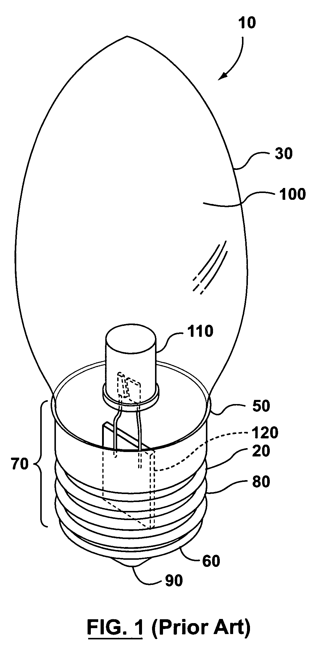
FIG. 1 illustrates an LED bulb according to the prior art. The LED bulb, generally shown as 10, comprises a hollow base 20 and a hollow shell or sometimes referred to as an envelope 30. For the instant application, the entire article illustrated, for example in FIG. 1, is called a bulb. The LED inside the bulb, for example LED 110, is called an LED. The base 20 has an open end 50, a closed end 60 and a sleeve 70 between the ends 50 and 60. The sleeve 70 has external threading 80 so as to match internal threading in a bulb holder (not shown) for installment. The sleeve 70 serves as an electrode. In the central part of the closed end 60 is located a contact point or portion, serving as another electrode 90, and an insulating portion (8171 in FIG. 7) separates and insulates the two parts 70 and 90. When the LED bulb 10 is installed in a bulb holder, such as in a desk lamp, parts 70 and 90, acting as electrodes, are connected to the electrical contact points in the bulb holder. The elec...


PUM


Abstract

An LED light bulb includes a base and a hollow shell. The base has a closed end, an open end and a sleeve between the two ends. The shell is connected to the open end of the base. The LED light bulb includes at least two LEDs substantially linearly arranged within the shell, and supported by a self-supporting wire connecting one terminal of an LED to the next LED in each strand.

Description

CROSS REFERENCEThis application is based on Republic of China (Taiwan) Application No. 0096206431 filed Apr. 23, 2007, the entirety of which is hereby incorporated by reference.FIELD OF THE INVENTIONThe present invention relates to a light bulb. In particular, the present invention relates to a light emitting diode (LED) light bulb that comprises one or more light emitting diodes (LEDs) in one or more substantially linear arrangements.BACKGROUND OF THE INVENTIONMost existing light bulbs are incandescent light bulbs or fluorescent light bulbs. An incandescent light bulb typically comprises a base, a glass shell, a thin filament which is normally a thin tungsten filament within the shell, and an inert gas within the shell. When an electric current passes through the tungsten filament and heats it up to an extremely high temperature (2000° C. to 3000° C. depending on the filament type, shape, size, and amount of current passed through), heat radiation occurs and visible light is produc...

Claims


Application Information

Patent Timeline
Patent Type & Authority Patents(United States)
IPC IPC(8): F21S4/00H01R33/945
CPCH05B33/0803H05B33/0809F21V3/00F21V3/02F21K9/1355F21V19/0005F21Y2111/001Y02B20/342Y02B20/383F21Y2101/02F21Y2105/00F21W2121/00F21Y2103/003F21K9/23F21Y2103/10F21Y2107/00F21Y2115/10H05B45/00H05B45/37Y02B20/30
Inventor NG, KAI KONGCHIANG, KUO-CHIU
Owner NG KAI KONG
Why Eureka
Try Eureka