Method and arrangement for controlling a drive arrangement in a watercraft

a technology for controlling a drive arrangement and a watercraft, which is applied in the direction of marine propulsion, vessel construction, instruments, etc., can solve the problems of watercraft being relatively low, the watercraft may sometimes deviate from a perfect sideways direction, and the driving maneuver can be quite difficult for the driver of the watercraft, etc., to achieve the effect of accurate watercraft driving

Active Publication Date: 2011-02-08
CPAC SYST
View PDF7 Cites 22 Cited by
  • Summary
  • Abstract
  • Description
  • Claims
  • Application Information

AI Technical Summary

Benefits of technology

[0006]A similar type of docking maneuver can also be obtained in watercraft provided with bow thrusters or stern thrusters. A bow thruster comprises a propeller which is mounted in the bow, generally transverse to the longitudinal direction of the watercraft, in order to generate a side force on the bow. In this manner, the watercraft can be more easily controlled when docking or maneuvering at low speeds. A similar arrangement, a so-called stern thruster, can be provided in the stern of a watercraft.
[0010]An object of the present invention is to provide a method and arrangement for operating a drive arrangement in a watercraft, by means of which the above-mentioned problem can be solved so that an accurate course of travel of a watercraft can be provided, in particular during docking of the watercraft.

Problems solved by technology

In certain situations, the docking maneuver can be quite difficult for the driver of the watercraft, for example when the watercraft must be landed with one of its sides towards the harbor, for example in a space between two other boats.
Assuming that the speed of the watercraft is relatively low, this will normally lead to a situation wherein the watercraft moves in a straight sideways direction.
However, during a docking maneuver, the movements of the watercraft may sometimes deviate from a perfect sideways direction.
For example, the watercraft may assume a direction of travel which follows a curved path, which obviously is a disadvantage.

Method used


Image

  • Method and arrangement for controlling a drive arrangement in a watercraft
  • Method and arrangement for controlling a drive arrangement in a watercraft
  • Method and arrangement for controlling a drive arrangement in a watercraft

Examples


Embodiment Construction

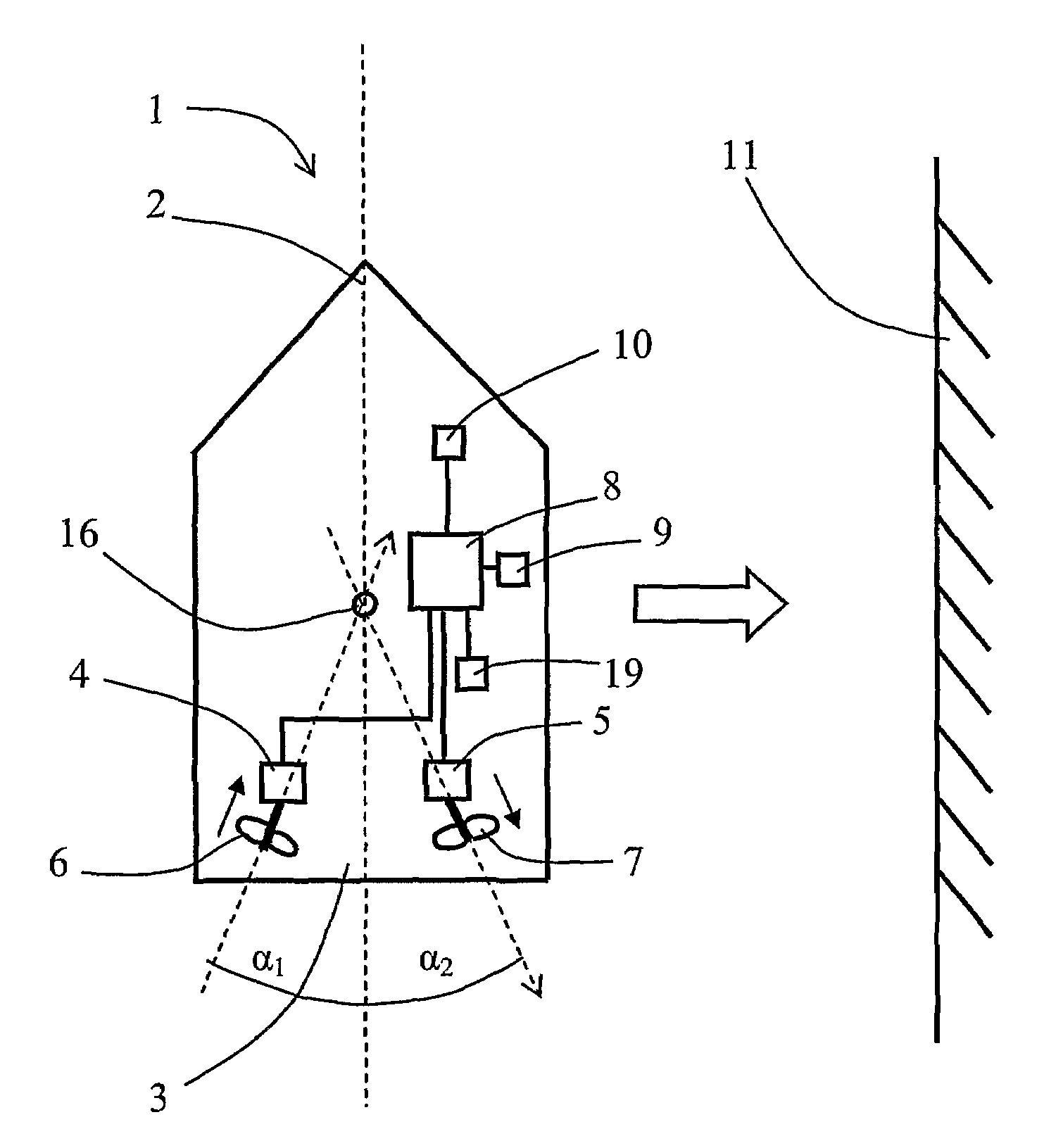
[0020]FIG. 1 shows a simplified top view of a watercraft 1 in which the present invention can be used. Generally, the invention can be used in any type of watercraft, such as larger commercial ships, smaller watercraft such as leisure boats and other types of water vehicles or vessels. The invention is particularly useful for small leisure boats, but it is nevertheless not limited to such type of water vehicle only.

[0021]As indicated schematically in FIG. 1, the watercraft 1 is designed with a bow 2 and a stern 3. In the stern 3, two drive arrangements 4, 5 are mounted. More precisely, the watercraft 1 is provided with a first drive arrangement 4 arranged at the port side and a second drive arrangement 5 arranged at the starboard side. The drive arrangements 4, 5 are generally of conventional kind, for example in the form of combustion engines or any other type of drive units suitable for marine applications. In this embodiment, the drive arrangements 4, 5 are in the form of combust...


PUM


Abstract

A method is provided for controlling a drive arrangement in a watercraft. The method includes detecting thrust and steering commands from an operating device which is connected to a control unit, and controlling the drive arrangement based on detected commands from the operating device for obtaining a desired course of travel of the watercraft, wherein a force is generated which acts towards a defined position on the watercraft. The method furthermore includes determining the speed of the watercraft and adapting the position on which the force from the drive arrangement acts as a function of at least the speed and as a function of the influence of the position of the center of pressure of the watercraft, thereby maintaining the desired course of travel. An arrangement for controlling a drive arrangement in a watercraft is also provided.

Description

BACKGROUND AND SUMMARY[0001]The present invention relates to a method for controlling a drive arrangement in a watercraft, comprising: detecting thrust and steering commands from an operating device which is connected to a control unit; controlling said drive arrangement based on detected commands from said operating device, for obtaining a desired course of travel of the watercraft, wherein a force is generated which acts towards a defined position on said watercraft; and determining the speed of the watercraft.[0002]The invention also relates to an arrangement for controlling a drive arrangement in a watercraft, comprising: an operating device for detecting thrust and steering commands; a control unit being arranged for controlling said drive arrangement based on detected commands from said operating device, for obtaining a desired course of travel of the watercraft, said control unit being arranged for generating a force which acts towards a defined position on said watercraft; a...

Claims


Application Information

Patent Timeline
Patent Type & Authority Patents(United States)
IPC IPC(8): B63H21/22B63H23/00G05D1/02
CPCB63H21/213G05D1/0206B63H25/46B63H25/42
Inventor LARSSON, ANDERS
Owner CPAC SYST
Why Eureka
Try Eureka