Helical conveyor centrifuge having a planetary gear drive device

a technology of planetary gear drive and centrifuge, which is applied in the direction of centrifuges, gearings, toothed gearings, etc., can solve the problems of difficult to set small differential speeds in a precise manner and difficult to standardize, and achieve the effect of simple and compact construction and precise setting of small differential speeds

Active Publication Date: 2011-02-08
GEA MECHANICAL EQUIP
View PDF25 Cites 4 Cited by
  • Summary
  • Abstract
  • Description
  • Claims
  • Application Information

AI Technical Summary

Benefits of technology

[0009]The present disclosure is different in that it provides for a helical conveyor centrifuge in which a relatively large differential speed can be set without an exchange of a secondary motor. The present disclosure reveals that it is possible to set even small differential speeds in a relatively simple and precise manner.
[0021]The desired differential speed can hence be set with high accuracy. In terms of power, the variable speed motor and the associated frequency converter can be accurately designed for the range of adjustment which is necessary from a process engineering perspective and are thus not dimensioned unnecessarily large. The remaining power is supplied by the drum motor. In an embodiment of the present disclosure, this leads to better overall efficiency.

Problems solved by technology

The problem here is that, in order to cover a greater range of adjustable differential speeds, it is necessary to use a variety of variable speed and secondary motors or a variety of gear ratios.
That makes standardization more difficult and, during operation, if a substantial change is made to the set differential speed, that may possibly necessitate a change of secondary motor.
The gearing additionally poses the problem, in that it is relatively difficult to set small differential speeds in a precise manner.
Moreover, the drawback, known from the prior art, that belt slippage, in the case of relatively small differential speeds, leads to unpredictable results, is avoided.

Method used


Image

  • Helical conveyor centrifuge having a planetary gear drive device
  • Helical conveyor centrifuge having a planetary gear drive device
  • Helical conveyor centrifuge having a planetary gear drive device

Examples


Embodiment Construction

[0031]FIGS. 1, 2 and 3a are described first.

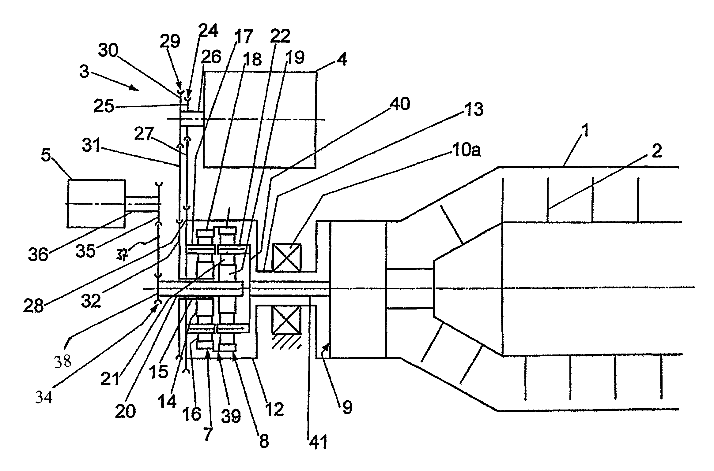
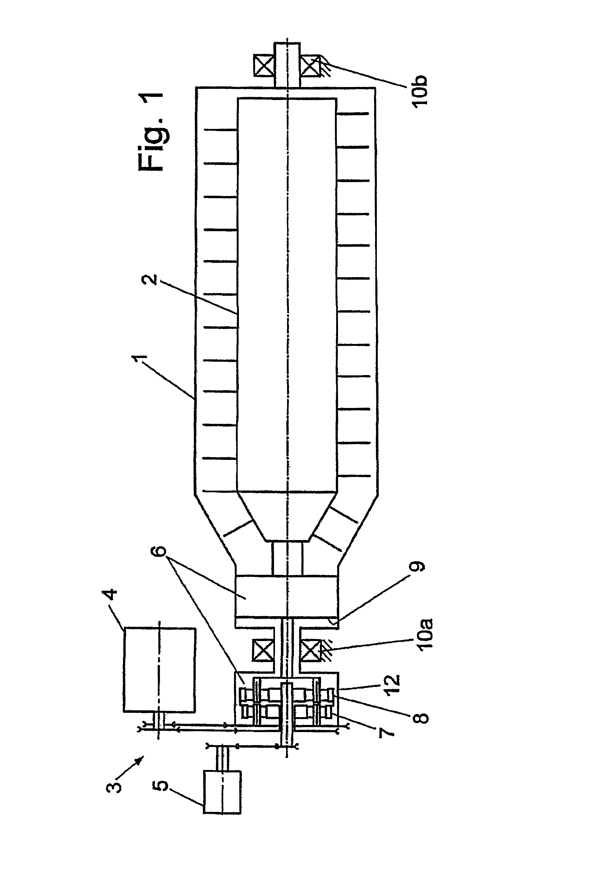
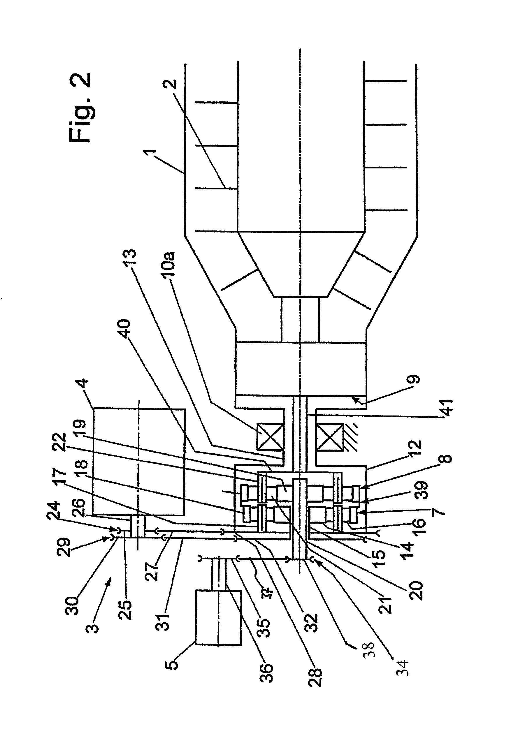
[0032]FIGS. 1 and 2 show a solid-bowl helical conveyor centrifuge comprising a rotatable drum 1, having a horizontal rotation axis, and a rotatable screw 2, which screw 2 is disposed within the drum 1 and has a centrifuge drive 3 for rotating the drum 1 and the screw 2. The drum 1 is disposed between drum bearings 10a, 10b, which are respectively arranged on a drive side and facing away from the centrifuge drive 3.

[0033]The centrifuge drive 3 includes a first motor 4, referred to as the main motor, and a second motor 5, referred to as the variable speed motor. Further included is a gearing arrangement disposed between the motors 4, 5 and also between the drum 1 and the screw 2.

[0034]The gearing arrangement may comprise only a single gearing 6 having three or more gear stages 7, 8, 9, which stages 7, 8, 9 are arranged downstream of the motors 4, 5. As shown in the embodiment, of FIGS. 1 and 2, the first two gear stages 7, 8 and the third ge...


PUM


Abstract

A helical conveyor centrifuge, such as a solid-bowl or sieve-bowl centrifuge, includes a rotatable drum, a rotatable screw disposed within the drum, and a centrifuge drive for rotating the drum and the screw. The centrifuge drive is configured to set a differential speed between drum and screw. The centrifuge drive includes a first motor, a second motor, and a gearing arrangement disposed between the motors and also between the drum and the screw. The gearing arrangement includes a gearing arranged downstream of the motors and has a first gear, a second gear and a third gear stage. The first and second gear stages include at least four shafts. Torques are either introduced into or are taken off from the first and second gear stages. The first and second gear stages are disposed in a housing and driven by at least three of the at least four shafts.

Description

BACKGROUND AND SUMMARY[0001]The present disclosure relates to a helical conveyor centrifuge.[0002]Such a centrifuge can be configured as a solid-bowl helical conveyor centrifuge or as a sieve-bowl helical conveyor centrifuge.[0003]DE 94 09 109 U1 discloses a centrifuge having an infinitely variable control of the differential speed between drum and broach.[0004]WO 94 / 23223 shows a planetary gearing which is used to drive helical conveyor centrifuges.[0005]From the magazine “Antriebstechnik 37 (1998, p. 39), a multistage differential gear drive is known. The gear drive has established itself as a gearing for driving decanters, since it allows a relatively good adjustment of differential speeds. As the preliminary stage it has a two-stage planetary gearing arrangement, which is configured as a four-shaft gearing, one shaft being secured during operation. The problem here is that, in order to cover a greater range of adjustable differential speeds, it is necessary to use a variety of v...

Claims


Application Information

Patent Timeline
Patent Type & Authority Patents(United States)
IPC IPC(8): B04B1/20B04B9/08
CPCB04B1/2016B04B2001/2025F16H37/0806
Inventor OVERBERG, MARTIN
Owner GEA MECHANICAL EQUIP
Why Eureka
Try Eureka