Method for manufacturing deicing acoustic skin for an aircraft acoustic panel, using a fiber spacing device

a technology of acoustic skin and fiber spacing, which is applied in the direction of efficient propulsion technologies, machines/engines, instruments, etc., can solve the problems of high noise, complex and long fitting of electric insulation, cost, complexity and time of manufacture, etc., and achieves the effect of reducing cost and simple and precise manner

Pending Publication Date: 2020-04-02
AIRBUS OPERATIONS (SAS)
View PDF1 Cites 1 Cited by
  • Summary
  • Abstract
  • Description
  • Claims
  • Application Information

AI Technical Summary

Benefits of technology

[0011]The present disclosure aims to overcome these disadvantages. It relates to a method for manufacturing a deicing acoustic skin, in particular for an acoustic attenuation panel of an aircraft, which makes it possible to manufacture a deicing acoustic skin in a simple and precise manner and at a reduced cost.

Problems solved by technology

It is known that, on an aircraft, for example on a transport plane, substantial noise is often produced, particularly via the propulsion assemblies (or jet engines) of the aircraft.
Fitting such electric insulation is complex and long.
The aforementioned processes for manufacturing an acoustic skin, in addition to having disadvantages in terms of cost, complexity and time of manufacture, cannot be used to form an acoustic skin which must also be a deicing skin.

Method used


Image

  • Method for manufacturing deicing acoustic skin for an aircraft acoustic panel, using a fiber spacing device
  • Method for manufacturing deicing acoustic skin for an aircraft acoustic panel, using a fiber spacing device
  • Method for manufacturing deicing acoustic skin for an aircraft acoustic panel, using a fiber spacing device

Examples


first embodiment

[0085]In a first embodiment represented in FIG. 8, the spacing device 5 is configured such that the pins 6 enter through the aerodynamic face 21A into the layer assembly 2. For this purpose, the spacing device 5 includes, in addition to the plate 9 supplied with the pins 6, a bearing tool 22, for example a plate, against which the layer assembly 2 bears via the rear face 21B thereof, and a guide 23 supplied with through-openings 24. The openings 24 have a shape and a diameter that are suited to those of the shank 12 of the pins 6 such as to allow the pins 6 to pass through while providing guiding.

second embodiment

[0086]Furthermore, in a second embodiment represented in FIG. 9, the spacing device 5 is configured such that the pins 6 enter through the rear face 21B into the layer assembly 2. For this purpose, the spacing device 5 includes, in addition to the plate 9 supplied with the pins 6, two guides 25 and 26 arranged on either side of the layer assembly 2, on the faces 21B and 21A, respectively. By way of illustration, FIG. 9 represents three different exemplary embodiments of the pins 6A, 6B and 6C.

[0087]The guide 25, through which the pins 6A, 6B and 6C are put into the layer assembly 2, is supplied with through-openings 27 with a shape and a diameter that are suited to those of the shank 12 of the pins such as to allow the pins 6A, 6B and 6C to pass through while being used as a guide.

[0088]The guide 26 is supplied with blind recesses 28A, 28B and 28C, with a shape and a diameter that are suited to the points 19A, 19B and 19C of the respective pins 6A, 6B and 6C such as to allow the poi...


PUM

PropertyMeasurementUnit
diameteraaaaaaaaaa
diameteraaaaaaaaaa
thicknessaaaaaaaaaa

Abstract

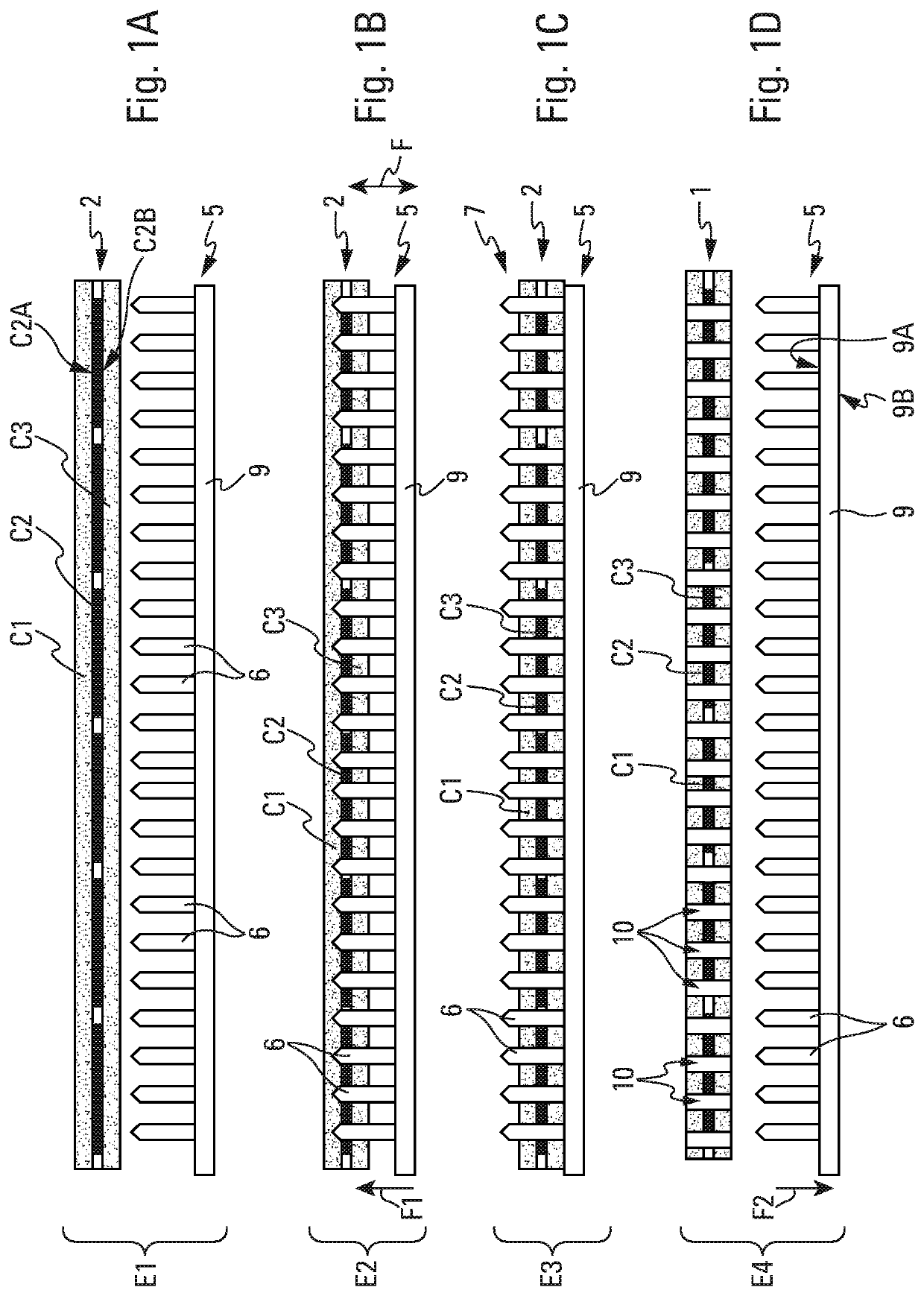
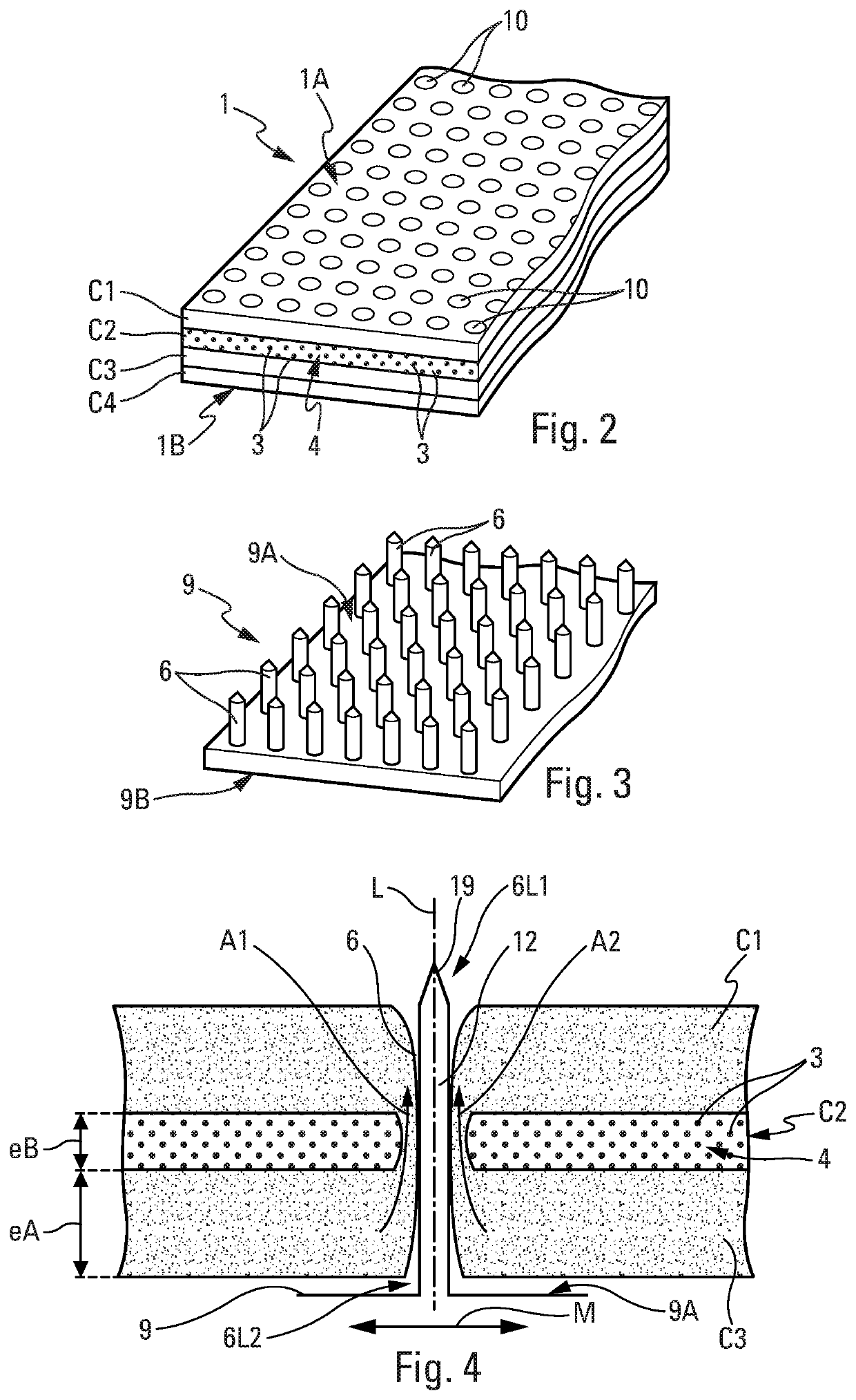
A method for manufacturing deicing acoustic skin for an aircraft acoustic panel, using a fiber spacing device. The manufacturing method includes at least one step for manufacturing a layer assembly having a deicing layer supplied with electrically conductive fibers embedded in a resin and two insulating layers arranged on either side of the deicing layer, and a baking step. The method provides for fitting, during baking, a spacing device on the layer assembly, the spacing device having pins passing through said layer assembly, perforations being produced at the locations of the pins after the withdrawal of the spacing device, the fitting of the spacing device making it possible to produce perforations with desired sizes and shapes, in a simple and effective manner, and with a reduced manufacturing duration.

Description

CROSS-REFERENCE TO PRIORITY APPLICATION[0001]This application claims the benefit of, and priority to, French patent application number 1859048, filed Oct. 1, 2018. The content of the referenced application is incorporated by reference herein.TECHNICAL FIELD[0002]Embodiments of the subject matter described herein relate generally to a method for manufacturing a deicing acoustic skin. This acoustic skin is preferably intended for an acoustic attenuation panel for an aircraft, and in particular for a jet engine nacelle cowl of an aircraft.BACKGROUND[0003]It is known that, on an aircraft, for example on a transport plane, substantial noise is often produced, particularly via the propulsion assemblies (or jet engines) of the aircraft. It is known, in order to reduce the sound effect produced by the jet engines of the aircraft, to provide, in particular at the nacelles of the jet engines, walls supplied with panels having good sound absorption. Conventionally, an acoustic attenuation pane...

Claims


Application Information

Patent Timeline
Patent Type & Authority Applications(United States)
IPC IPC(8): B29C70/88B64D33/02
CPCB64D2033/0206B29C70/882B64D2033/0233B64D33/02B64C1/12B64C1/40B64D15/12B64F5/10F02C7/045F02C7/047F05D2250/191F05D2260/963F05D2300/44F05D2300/603B32B3/266B32B3/12B32B2307/102B32B2605/18B32B2307/30G10K11/168Y02T50/60B29C65/02B32B37/06B32B2038/047B32B2305/02B32B2305/07B32B2305/38B32B2313/04B29C70/545
Inventor PORTE, ALAINLALANE, JACQUESMENAY, HASSAN
Owner AIRBUS OPERATIONS (SAS)
Why Eureka
Try Eureka