Hydraulic-control limited rotational speed difference differential

A differential, limited technology, applied in the direction of differential transmission, belt/chain/gear, mechanical equipment, etc., can solve the problems of differential speed, differential force, large torque, etc., to prevent the differential speed from being too large, Low production cost and effect of differential force function

Inactive Publication Date: 2013-12-25
DALIAN UNIV OF TECH
View PDF7 Cites 0 Cited by
  • Summary
  • Abstract
  • Description
  • Claims
  • Application Information

AI Technical Summary

Problems solved by technology

[0003] The technical problem to be solved by the present invention is: through the rational combination of cylindrical gears, not only can realize the two working states of the same speed output and differential speed output of the two shafts under the condition of single power source input, but also overcome the The characteristic defect of "differential force without differential force" that is difficult to overcome by ordinary differentials can better realize the adaptive conversion of the three states in the working process of the differential: that is, when the resistance of the two output shafts is the same, the two shafts rotate synchronously; the two output shafts rotate synchronously; There is a small difference in shaft resistance, and when the speed difference between the two output shafts is small, the two shafts can perform differential motion; and when the speed difference between the two output shafts is large to a certain extent, the characteristics of "differential speed and differential force" are realized, and the two shafts There can be large torque differences

Method used


Image

  • Hydraulic-control limited rotational speed difference differential
  • Hydraulic-control limited rotational speed difference differential
  • Hydraulic-control limited rotational speed difference differential

Examples


Embodiment 1

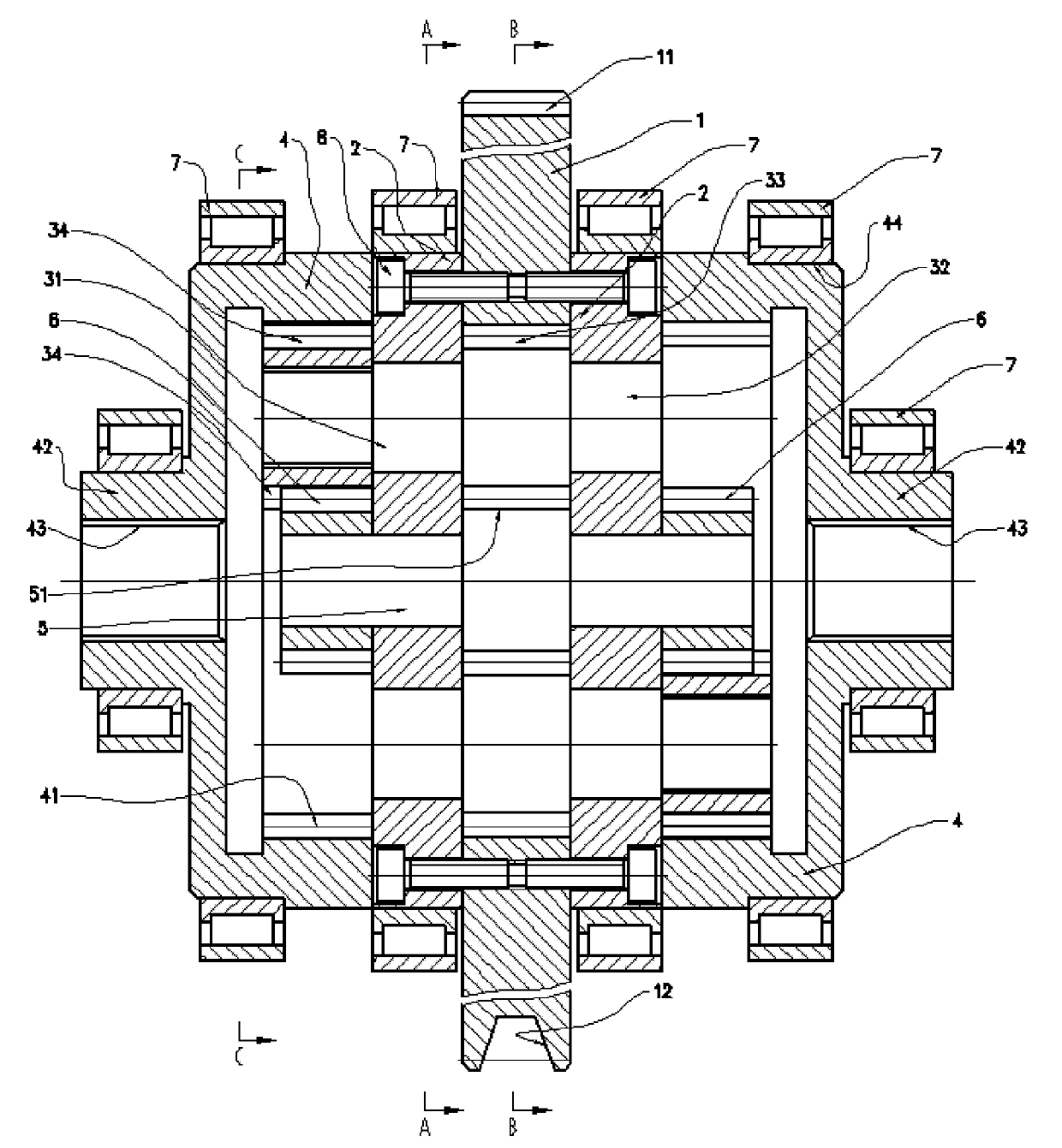
[0016] figure 1 In the figure, the upper part of the outer circle of the power input wheel is the tooth of the cylindrical gear, and the lower part is the groove of the pulley; the inner hole of the power input wheel in the figure is a round hole, and the closed shaft is an independent cylindrical shape .

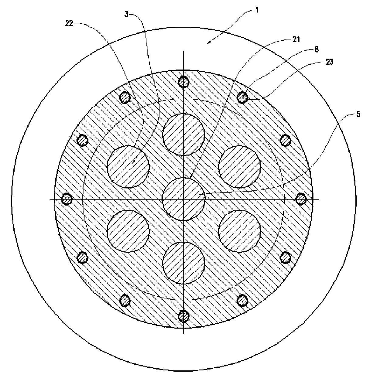
[0017] Such as figure 1 As shown, the power input wheel 1, two disc-shaped cover plates 2, three to six pairs of double planetary gear assemblies 3, two output wheels 4 composed of internally toothed cylindrical gears, a central closed shaft 5 and a central gear 6 and The bearing 7, the connecting screw 8 and the shell that are used to support the rotation of each part are formed.

[0018] The power input wheel 1 is ring-shaped, with gear teeth 11 or wheel grooves 12 on the outer edge to realize power input, and the inner hole is a round hole 14 or an outer crescent-shaped hole 15; Fix the disc-shaped cover plate 2 with the threaded hole 23 on the cover plate 2. There is...

Embodiment 2

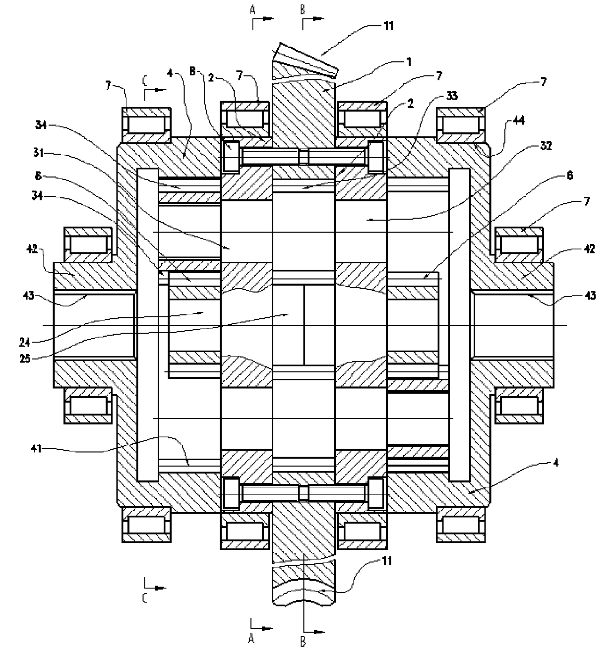
[0020] figure 2 , the upper part of the outer edge of the power input wheel is the tooth of the bevel gear, and the lower part is the tooth of the worm wheel; and for figure 1 The structure of the cover plate has been changed: the inner and outer sides of the central part of the disc-shaped cover plate are made into raised shaft sections to complete figure 1 Central closed shaft function, the center gear is installed on the central shaft of the cover plate protruding outside the cover plate, and the protruding shaft section inside the cover plate is a crescent-shaped closed shaft inside the cover plate.

[0021] Such as figure 2 As shown, this embodiment and figure 1 The difference is: the power input wheel 1 is ring-shaped, and its outer edge can be the upper half of the gear tooth 11 figure of the bevel gear, or the lower half of the gear tooth figure of the worm gear, and the power input is realized by the power input wheel 1. The cylindrical surface of the inner hole ...


PUM


Abstract

A hydraulic-control limited rotational speed difference differential transmission device is used in a transmission system for resolving and transmitting one revolution motion to two output shafts, and is typically applied in the dynamic input and the differential output for a vehicle driving wheel. In the invention, twelve respective sealed spaces are formed between a wheel train comprising a plurality of cylindrical gears and two plate-shaped cover plates, so as to convert the three operation states of the differential in a self adapting manner, that is, when the resistance of the two output shafts is the same, the two shafts turn around synchronously; when the difference of the resistance of the two output shafts is small and the difference of the rotational speed of the two input shafts is smaller, oil flows from six high-pressure zones to six low-pressure zones through a clearance, the flowing resistance of liquid is smaller, differential motion of the two shafts is realized; and when the rotational speed difference of the two output shafts is bigger, the flowing resistance of liquid is obviously increased, so that the differential speed of the two output shafts is prevented from being too big, the two shafts can transmit different rotary moment and effectively transmit dynamic force, as a result, the characteristic of differential speed and differential driving force is realized, the problem of differential speed and no driving force difference of the common differential is solved, the market prospect is wide.

Description

technical field [0001] The invention relates to a transmission device, which is used in a transmission system to transmit the same rotary motion to two output shafts at the same time. The two output shafts can rotate synchronously and at the same time allow the two output shafts to have a certain degree of speed difference. The typical application is The power input of the drive wheels of the vehicle and the realization of differential motion. Background technique [0002] When the power is input from one wheel, and two shafts are required to be output, and the two output wheels sometimes need to run synchronously, and sometimes must meet certain differential speed requirements, a differential must be used. The typical structure of the commonly used differential was invented by Louis Renault, the founder of the French Renault Motor Company a hundred years ago, and its basic components are bevel gears and cross shafts. Its characteristic is that the differential speed is not...

Claims


Application Information

Patent Timeline
Patent Type & Authority Patents(China)
IPC IPC(8): F16H48/11F16H48/32
Inventor 杨光辉孙守林
Owner DALIAN UNIV OF TECH
Why Eureka
Try Eureka