Device and method for cooling components using magnetizable phase-change material

a phase-change material and device technology, applied in the direction of indirect heat exchangers, semiconductor/solid-state device details, lighting and heating apparatus, etc., can solve the problems of high-integrated electronic circuits that may heat up very quickly, premature ageing and breakdown of the entire sub-assembly, and relatively high elements cost. , to achieve the effect of increasing latent-heat storage capacity, high heat flow, and simple and precise manner

Inactive Publication Date: 2014-11-04
ROBERT BOSCH GMBH
View PDF19 Cites 1 Cited by
  • Summary
  • Abstract
  • Description
  • Claims
  • Application Information

AI Technical Summary

Benefits of technology

[0019]Another advantage consists of the fact that the example device operates without noise and is resistant to mechanical and chemical actions and also does not have any elements exhibiting wear. In addition, the required electrical power consumption for rotating the solid portion of the phase-change material, which is acting as positive-displacement piston and has a magnetic orientation, is very low.
[0020]Another advantage is that pumps, hose connections, compression packing or screw connections, which have to be provided for convective cooling systems, are not required. The phase-change material is hermetically sealed inside a solid housing. Given appropriate internal-pressure stability of the housing, the liquid phase and the gaseous phase of the phase-change material are unable to leave the housing.
[0023]Another advantage of the ferromagnetic or magnetizable particles in the phase-change material is that the heat absorbed or dissipated by melting and solidification, respectively, and the discharged and incoming heat flows are able to be measured in a simple and precise manner via an attendant change in the magnetization of the phase-change material, based on the change in the coil inductivities. In addition, the temperature of the heat sink and the heat source may be determined from the heat flow balance and known thermal material parameters of the housing and the phase-change material. The clock rate of the recirculation cycle is controlled with the aid of these quantities, thereby ensuring that sufficient solid phase of the phase-change material is always available in the immediate environment of the heat source, and that a high heat flow is maintained at the heat source.
[0024]In order to ensure the recirculation of the phase-change material, it is preferred if the cavity which holds the phase-change material has a circular cross-section. The two coils, which enclose the cavity containing the phase-change material, are preferably aligned relative to each other such that the magnetic fields generated by the coils may have the same orientation. The coils are preferably disposed in such a way that one coil is situated above a center plane of the cavity, and the other coil is situated below the center plane of the cavity. This placement of the coils makes it possible to realize the rotation of the unmelted, magnetically oriented portion of the phase-change material with the aid of appropriate control and alignment of the magnetic field.
[0025]In one specific embodiment, in order to increase the latent-heat storage capacity, it is possible to place at least two cavities containing phase-change material one after the other in the transport direction of the heat. In the process, the phase-change material situated in each cavity is able to absorb heat and store it. By rotation and subsequent solidification, the heat is then dissipated again. If a large surface has to be cooled, it is also possible to place a plurality of cavities containing phase-change material next to each other. Even in the case of non-planar surfaces, this makes it possible to achieve a placement that ensures optimum cooling, since in the case of adjacently disposed cavities in which phase-change material is contained, the cavities may also be placed at different levels and thus be adapted to the surface of the component to be cooled.

Problems solved by technology

When the electrical power consumption is high and, in particular, when transient load states occur, highly integrated electronic circuits may heat up very quickly due to the unavoidable Ohmic and dielectric losses.
However, excessively high internal temperatures at the pn-junctions of the semiconductors can lead to malfunctions, premature ageing and breakdown of the entire subassembly, which is why the internal thermal energy must be dissipated to the system environment.
However, these elements are relatively expensive, increase the electrical power consumption of the electronics, and possibly use more space themselves than the electronic components to be cooled.
For this reason, Peltier elements are not an option for wide-spread use.
However, when thermal contact to the system environment is technically not feasible or not desired, latent heat stores, which absorb the heat from a heat source, may be used.
For example, in a temporary rapid increase in the ambient temperatures, e.g., while driving slowly or while the vehicle is standing following a longer operating period in the full-load state of the engine, cooling by diffusion or air convection of electronic control devices in an engine compartment of a motor vehicle may possibly no longer be sufficient.
However, in the boundary layer to the heat source, the local temperature of the liquid phase, for example, may become higher than the melting temperature as the layer thickness increases, due to its poorer thermal conductivity in comparison with the solid phase.
For example, these peaks occur during a regeneration operation of Diesel particulate filters having a plurality of electronically controlled post-injections of the engine, or following longer operation in the full-load range of the motor and subsequent slow driving or stop-and-go driving while high temperatures are prevailing in the engine and poor air convection exists at the same time.
The example device may be used in applications, for example, that do not allow a recirculation of fluid or gaseous coolant media driven by positive-displacement or turbo pumps.
In addition, the required electrical power consumption for rotating the solid portion of the phase-change material, which is acting as positive-displacement piston and has a magnetic orientation, is very low.
In addition to cooling and temperature stabilization of electronic control devices in motor vehicles, the device for cooling components is also suitable for cooling compact, integrated electrical, micromechanical, and electronic subassemblies, which heat up rapidly due to the low mass and heat capacity of the subassembly at thermal load peaks, and which leave no room for driven convection cooling systems, or are unable to provide sufficient electric drive output and / or do not allow for a heat transfer to the immediate system environment due to a thermally unfavorable installation location or structural marginal conditions.
Heat transfer to the immediate system environment is impossible, for example, when increased ambient temperatures or mechanical stresses exist temporarily, or when thermal conduction is insufficient due to high thermal transfer resistances.

Method used


Image

  • Device and method for cooling components using magnetizable phase-change material
  • Device and method for cooling components using magnetizable phase-change material
  • Device and method for cooling components using magnetizable phase-change material

Examples


Embodiment Construction

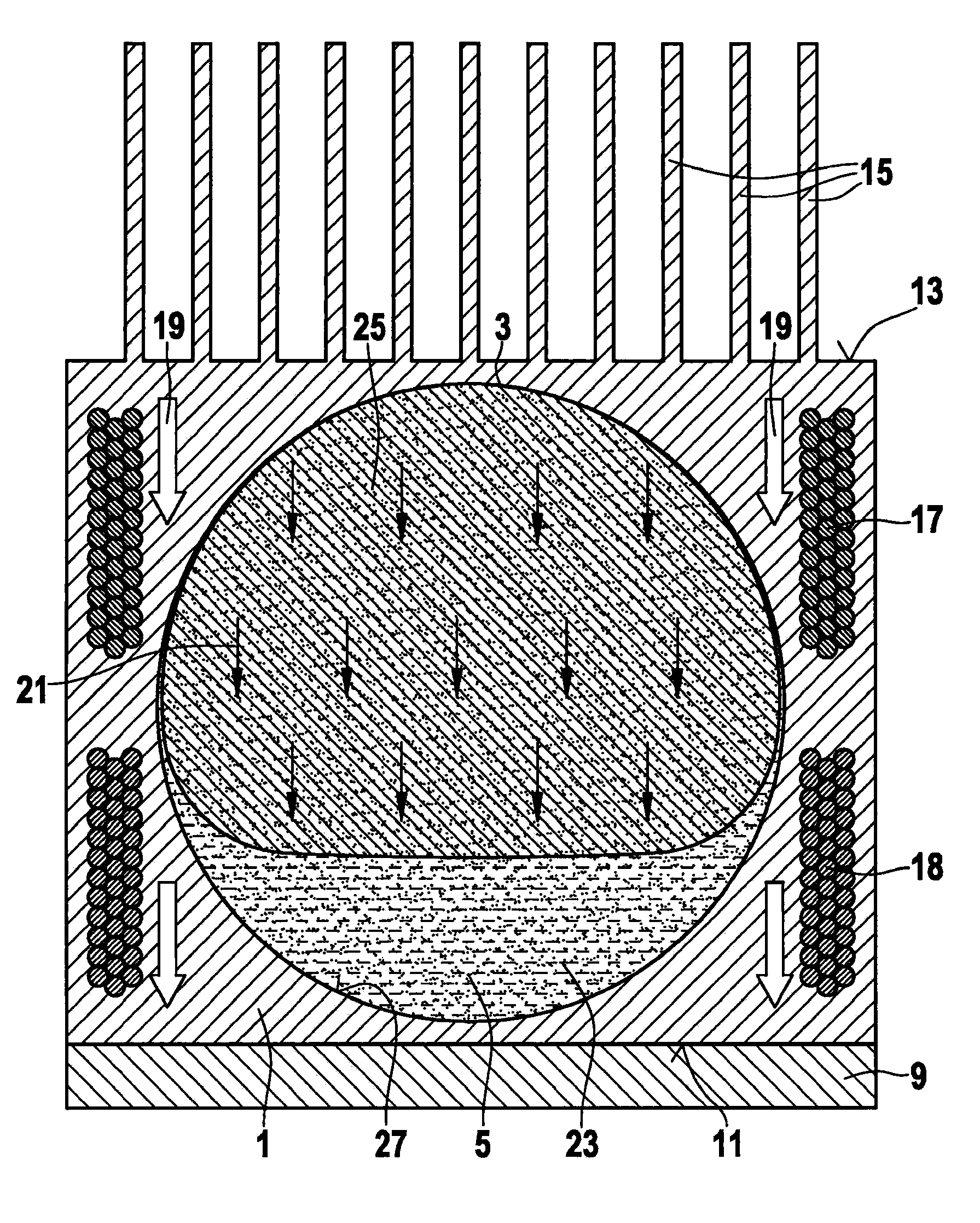
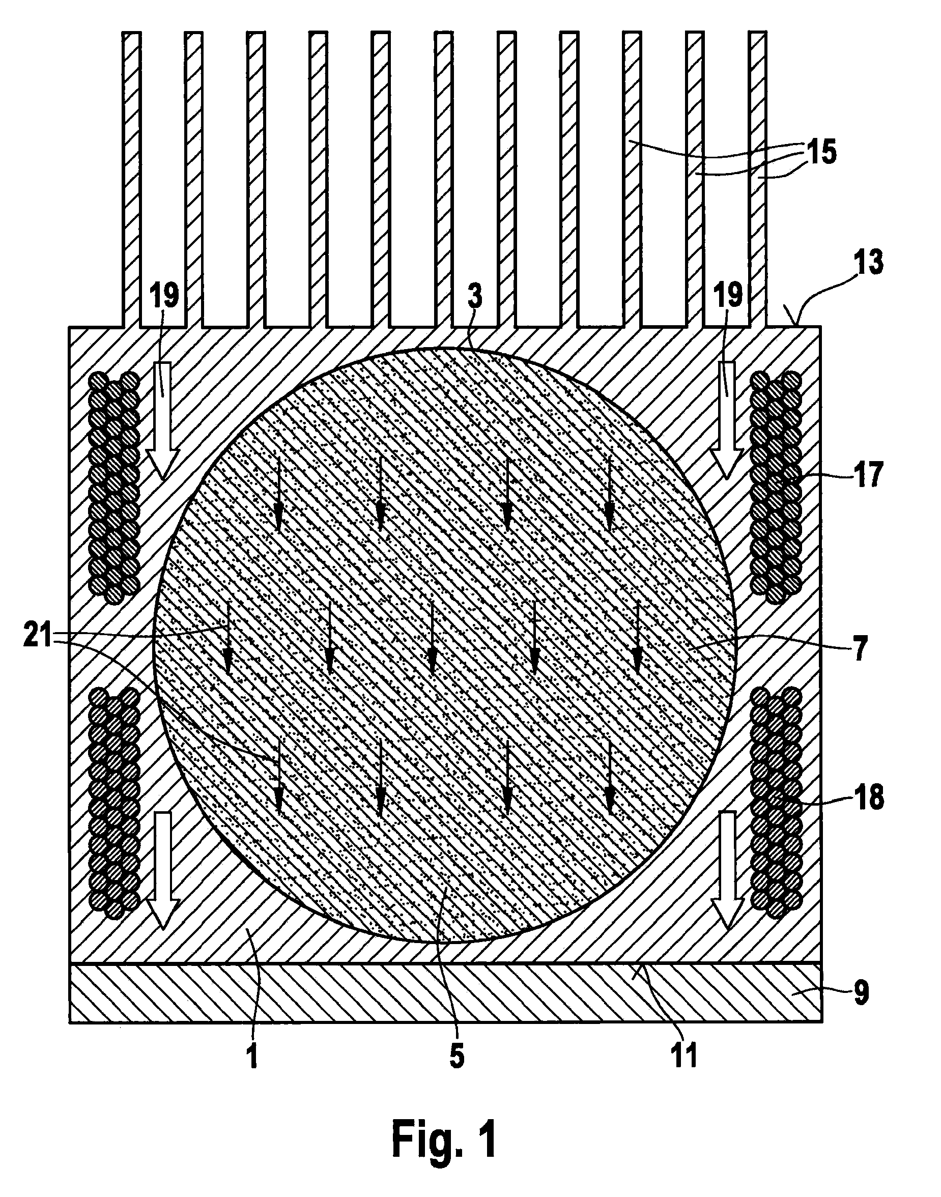
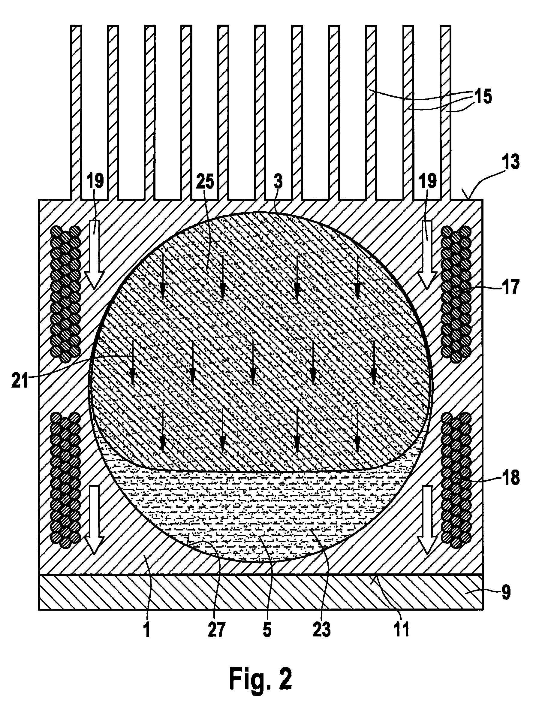
[0036]In FIGS. 1 through 6, a method for cooling components in a device for cooling components is shown in a first specific embodiment.

[0037]An example device designed for cooling components according to the present invention includes a housing 1, which made of a material having excellent thermal conductivity. Metal materials are particularly suitable for housing 1. Especially suitable is copper or aluminum, for example. A cavity 3 is formed in the housing. In the specific development illustrated here, cavity 3 has a circular cross-section. Cavity 3 developed with a circular cross-section may be in the shape of a cylinder, a ball, or also have a conical form or the form of a truncated cone. Preferably, however, cavity 3 is spherical or cylindrical. Contained in cavity 3 is a phase-change material 5. Employed phase-change material 5 is a function of the temperature of the component to be cooled. For example, paraffin, waxes, grease, fatty acids, metal alloys such as bismuth-lead allo...


PUM

PropertyMeasurementUnit
particle diameteraaaaaaaaaa
magnetic fieldaaaaaaaaaa
magnetizationaaaaaaaaaa

Abstract

A device for cooling components, comprising a housing in which a cavity is formed, in which a phase-change material is accommodated, the housing having at least one surface, which is able to be brought into contact with the component to be cooled, and at least one heat-dissipating surface. The cavity accommodating the phase-change material is enclosed by at least one coil, and the phase-change material includes ferromagnetic or magnetizable particles. Furthermore a method for cooling a component using the device is described.

Description

FIELD OF THE INVENTION[0001]The present invention is based on a device and method for cooling components.BACKGROUND INFORMATION[0002]Components that need to be cooled are, for instance, compact electronic subassemblies having highly-integrated circuits (ASICs), and digital microcontrollers in which high power-loss densities could occur. When the electrical power consumption is high and, in particular, when transient load states occur, highly integrated electronic circuits may heat up very quickly due to the unavoidable Ohmic and dielectric losses. However, excessively high internal temperatures at the pn-junctions of the semiconductors can lead to malfunctions, premature ageing and breakdown of the entire subassembly, which is why the internal thermal energy must be dissipated to the system environment.[0003]The heat dissipation takes place by passive diffusion cooling, for example, or by the technically complex convective coolant recirculation with the aid of turbo or positive-disp...

Claims


Application Information

Patent Timeline
Patent Type & Authority Patents(United States)
IPC IPC(8): F28F7/00H01L23/427F25B21/00H01L23/373H01F5/00F28F13/16F28D20/02F28F27/00
CPCF28F13/16Y02E60/145H01L23/4275F28D20/028F28D20/02H01L23/3736H01L2924/0002F28F13/125Y02E60/14H01L2924/00
Inventor DANNER, REINHOLDLISCHECK, ANDRESCHULZ, UDOPROEPPER, THOMASBARTH, HEINRICH
Owner ROBERT BOSCH GMBH
Why Eureka
Try Eureka