
Method and system for providing continuous calibration of implantable analyte sensors

a technology of analyte sensor and continuous calibration, which is applied in the field of ##uous monitoring of analytes, can solve the problems of gap in service, patient inability to monitor or determine analyte values such as glucose levels, and interruption of analyte monitoring or monitoring

Active Publication Date: 2011-02-08
ABBOTT DIABETES CARE INC
View PDF739 Cites 188 Cited by
  • Summary
  • Abstract
  • Description
  • Claims
  • Application Information

AI Technical Summary

Problems solved by technology

During the sensor replacement process, a gap or interruption in the analyte monitoring occurs.
For example, during the time period in which the patient removes the implanted analyte sensor to replace with a new analyte sensor, the patient is unable to monitor or determine the analyte values such as glucose levels.
In this manner, with continuous glucose monitoring systems presently available which use short term analyte sensors, there is always a gap in service during which data associated with the measurement of the patient's analyte levels cannot be obtained.
In addition, calibration of each implanted analyte sensor, which is necessary before data from the analyte sensor can be obtained, is laborious, time consuming, and error prone.
Factory calibration is not a practical approach due to substantial sensor to sensor variability of signal strength introduced during the manufacturing process, and also, due to additional variability imposed by the sensors' response to the in-vivo environment which varies from patient to patient.
Moreover, calibrations may sometimes be inaccurate due to transient sensitivity changes which generally occur early in the lifetime of an implanted sensor, and sometimes referred to as early sensitivity attenuation, or ESA.
If a calibration is assigned to an analyte sensor undergoing a transient change in sensitivity, inaccurate sensor readings or measurements will result at a later point in time, when the sensitivity reverts to its “true” value.

Method used


Image

  • Method and system for providing continuous calibration of implantable analyte sensors
  • Method and system for providing continuous calibration of implantable analyte sensors
  • Method and system for providing continuous calibration of implantable analyte sensors

Examples


Embodiment Construction

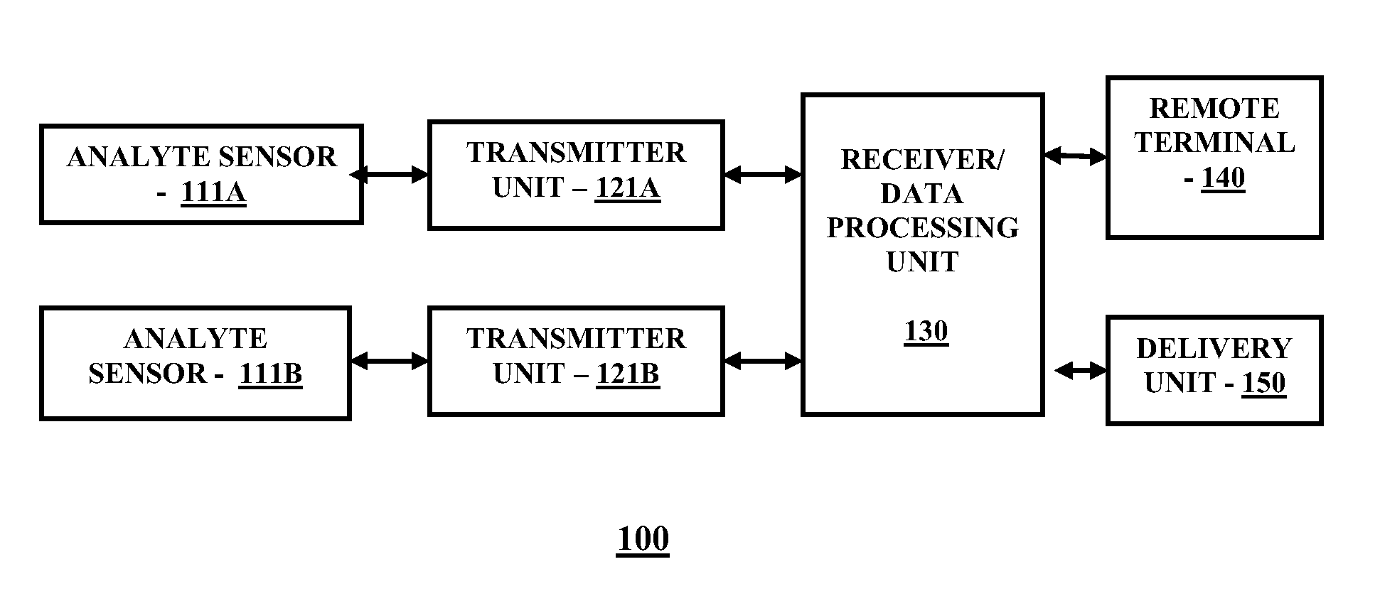
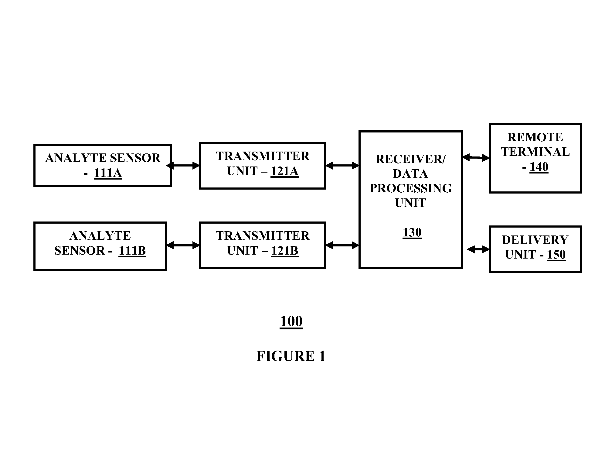
[0017]FIG. 1 is a block diagram illustrating a continuous analyte monitoring system for practicing one embodiment of the present invention. Referring to FIG. 1, a continuous analyte monitoring system 100 includes analyte sensor 111A operatively coupled to a transmitter unit 121A, and analyte sensor 111B operatively coupled to transmitter unit 121B. Further shown is a receiver / data receiving unit 130 which is operatively coupled to transmitter unit 121A and transmitter unit 121B. The receiver / data processing unit 130 in one embodiment is configured to communicate with a remote terminal 140 and a delivery unit 150. The remote terminal 140 in one embodiment may include for example, a desktop computer terminal, a data communication enabled kiosk, a laptop computer, a handheld computing device such as a personal digital assistant (PDAs), or a data communication enabled mobile telephone. Moreover, the delivery unit 150 may include in one embodiment, but not limited to, an external infusio...


PUM


Abstract

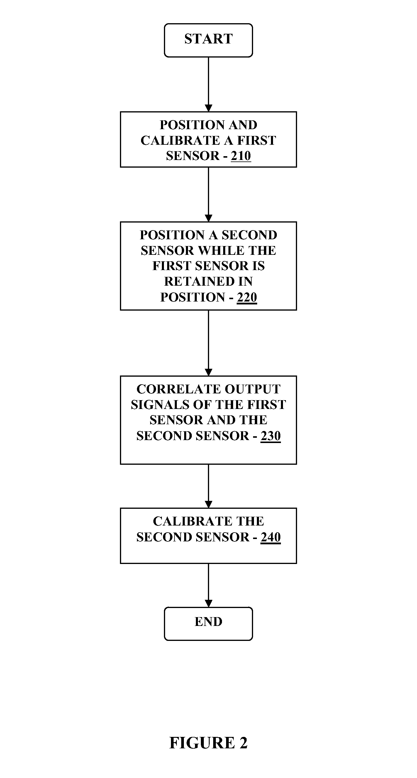
Method and system for providing continuous calibration of analyte sensors includes calibrating a first sensor, receiving data associated with detected analyte levels from the first sensor, and calibrating a second sensor based on a predetermined scaling factor and data associated with detected analyte levels from the first sensor, is disclosed.

Description

BACKGROUND[0001]Continuous monitoring of analytes of a patient generally uses an analyte sensor that that is at least partially implanted in the patient so as to be in fluid contact with the patient's analytes such as interstitial fluid or blood. The analyte sensor typically is replaced after a predetermined time period such as three, five or seven day period, when a new sensor is implanted in the patient to replace the old sensor. During the sensor replacement process, a gap or interruption in the analyte monitoring occurs. For example, during the time period in which the patient removes the implanted analyte sensor to replace with a new analyte sensor, the patient is unable to monitor or determine the analyte values such as glucose levels. In this manner, with continuous glucose monitoring systems presently available which use short term analyte sensors, there is always a gap in service during which data associated with the measurement of the patient's analyte levels cannot be obt...

Claims


Application Information

Patent Timeline
Patent Type & Authority Patents(United States)
IPC IPC(8): A61B5/00
CPCA61B5/0031A61B5/6846A61B5/1495A61B5/14532A61B2560/0223G16H50/20H04L67/12A61B5/0017A61B5/0024A61B5/14503A61B5/7246A61M5/1723
Inventor FELDMAN, BENJAMIN J.
Owner ABBOTT DIABETES CARE INC
Learn More