Nerve stimulation for treating disorders

a nerve stimulation and nerve technology, applied in the field of treating patients, can solve problems such as blocking of smaller-diameter fibers, and achieve the effects of reducing heart rate variability, increasing variability, and modifying heart rate variability of subjects

Inactive Publication Date: 2011-02-08
MEDTRONIC INC
View PDF198 Cites 147 Cited by
  • Summary
  • Abstract
  • Description
  • Claims
  • Application Information

AI Technical Summary

Benefits of technology

[0194]In some embodiments of the present invention, apparatus for treating a heart condition comprises a multipolar electrode device that is applied to a portion of a vagus nerve that innervates the heart of a patient. Typically, the system is configured to treat heart failure and / or heart arrhythmia, such as atrial fibrillation or tachycardia. A control unit typically drives the electrode device to (i) apply signals to induce the propagation of efferent action potentials towards the heart, and (ii) suppress artificially-induced afferent and efferent action potentials, in order to minimize any unintended side effect of the signal application. Alternatively, the control unit drives the electrode device to apply signals that induce symmetric or asymmetric bi-directional propagation of nerve impulses.
[0195]The control unit typically suppresses afferent action potentials induced by the cathodic current by inhibiting essentially all or a large fraction of fibers using anodal current (“afferent anodal current”) from a second set of one or more anodes (the “afferent anode set”). The afferent anode set is typically placed between the central cathode and the edge of the electrode device closer to the brain (the “afferent edge”), to block a large fraction of fibers from conveying signals in the direction of the brain during application of the afferent anodal current.
[0197]In some embodiments of the present invention, the efferent anode set comprises a plurality of anodes. Application of the efferent anodal current in appropriate ratios from the plurality of anodes in these embodiments generally minimizes the “virtual cathode effect,” whereby application of too large an anodal current creates a virtual cathode, which stimulates rather than blocks fibers. When such techniques are not used, the virtual cathode effect generally hinders blocking of smaller-diameter fibers, because a relatively large anodal current is typically necessary to block such fibers, and this same large anodal current induces the virtual cathode effect. Likewise, the afferent anode set typically comprises a plurality of anodes in order to minimize the virtual cathode effect in the direction of the brain.
[0203]Advantageously, the techniques described herein generally enable relatively fine control of the level of stimulation of the vagus nerve, by imitating the natural physiological smaller-to-larger diameter recruitment order of nerve fibers. This recruitment order allows improved and more natural control over the heart rate. Such fine control is particularly advantageous when applied in a closed-loop system, wherein such control results in smaller changes in heart rate and lower latencies in the control loop, which generally contribute to greater loop stability and reduced loop stabilization time.
[0297]For some applications, the control unit is adapted to configure the stimulating current to suppress inflammation sufficiently to treat atrial fibrillation of the subject. For some applications, the control unit is adapted to configure the stimulating current to reduce thromboembolism of the subject. For some applications, the control unit is adapted to configure the stimulating current to increase a likelihood of successful cardioversion.

Problems solved by technology

When such techniques are not used, the virtual cathode effect generally hinders blocking of smaller-diameter fibers, because a relatively large anodal current is typically necessary to block such fibers, and this same large anodal current induces the virtual cathode effect.

Method used


Image

  • Nerve stimulation for treating disorders
  • Nerve stimulation for treating disorders
  • Nerve stimulation for treating disorders

Examples


Embodiment Construction

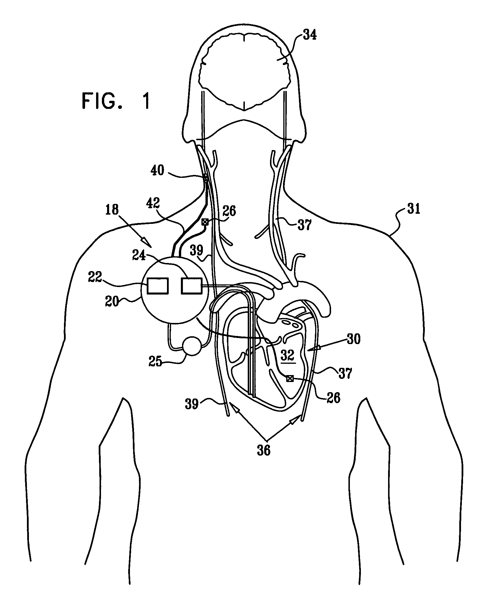
[0435]FIG. 1 is a block diagram that schematically illustrates a vagal stimulation system 18 comprising a multipolar electrode device 40, in accordance with an embodiment of the present invention. Electrode device 40 is applied to a portion of a vagus nerve 36 (either a left vagus nerve 37 or a right vagus nerve 39), which innervates a heart 30 of a patient 31. Typically, system 18 is utilized for treating a heart condition such as heart failure and / or cardiac arrhythmia. Vagal stimulation system 18 further comprises an implanted or external control unit 20, which typically communicates with electrode device 40 over a set of leads 42. For some applications, control unit 20 drives electrode device 40 to (i) apply signals to induce the propagation of efferent nerve impulses towards heart 30, and (ii) suppress artificially-induced afferent nerve impulses towards a brain 34 of the patient, in order to minimize unintended side effects of the signal application. Alternatively, control uni...


PUM


Abstract

This invention provides a method for treating a condition of a subject, comprising identifying the subject as suffering from heart failure; treating the heart failure by applying a stimulating current to parasympathetic nervous tissue of the subject, and configuring the stimulating current to change a level of protein expression of at least one NO synthase of the subject selected from the group consisting of: NOS-1, NOS-2, and NOS-3; and thereafter, measuring the level of the protein expression of at least one NO synthase, and evaluating an effectiveness of the current application by assessing at least one change in the level of the protein expression of at least one NO synthase.

Description

CROSS-REFERENCES TO RELATED APPLICATIONS[0001]This application claims the benefit of U.S. Provisional Application Nos. 60 / 668,275, filed Apr. 4, 2005 and 60 / 612,428, filed Sep. 23, 2004, the contents of which are hereby incorporated by reference into this application.FIELD OF THE INVENTION[0002]The present invention relates generally to treating patients by application of electrical signals to a selected nerve or nerve bundle, and specifically to methods and apparatus for stimulating the vagus nerve for treating heart conditions.BACKGROUND OF THE INVENTION[0003]The use of nerve stimulation for treating and controlling a variety of medical, psychiatric, and neurological disorders has seen significant growth over the last several decades. In particular, stimulation of the vagus nerve (the tenth cranial nerve, and part of the parasympathetic nervous system) has been the subject of considerable research. The vagus nerve is composed of somatic and visceral afferents (inward conducting ne...

Claims


Application Information

Patent Timeline
Patent Type & Authority Patents(United States)
IPC IPC(8): A61N1/36
CPCA61N1/36071A61N1/36114
Inventor BEN-DAVID, TAMIR
Owner MEDTRONIC INC
Why Eureka
Try Eureka