User interface for demand side energy management

a technology for demand side energy management and user interfaces, applied in the field of electric power, can solve the problems of cumbersome manual energy management, inability to perform remote, and high cost of electric power consumption for the average consumer, and achieve the effect of saving energy bills

Active Publication Date: 2011-02-08
GRIDPOINT
View PDF13 Cites 133 Cited by
  • Summary
  • Abstract
  • Description
  • Claims
  • Application Information

AI Technical Summary

Benefits of technology

[0007]In one embodiment, the invention provides a cohesive, intuitive, and graphically rich consumer interface for demand-side energy management. The interface allows users to construct energy schedules and rule-sets for their thermostats as well as specify ‘off’ periods for other household circuits on a scheduled and / or rule-driven basis. By allowing users to program their thermostats while also turning off circuits during times that they are not home or when the price of energy reaches or exceeds certain levels, users will realize savings on their energy bills.

Problems solved by technology

The cost of electric power consumption represents a significant expense for the average consumer.
Managing energy consumption manually is, however, cumbersome, and cannot be performed remotely.
However, none of these elements are treated in a unified fashion within the context of an overarching energy profile which allows for thermostats and device relays to be controlled in concert and on a scheduled or rule-driven basis.
While the concept of integrating these components has been considered within the context of utility demand response programs, none of these programs expose either the interface, notion, or control to the end customer, nor do they serve the customer's interests in monitoring and reducing energy usage.

Method used


Image

  • User interface for demand side energy management
  • User interface for demand side energy management
  • User interface for demand side energy management

Examples


Embodiment Construction

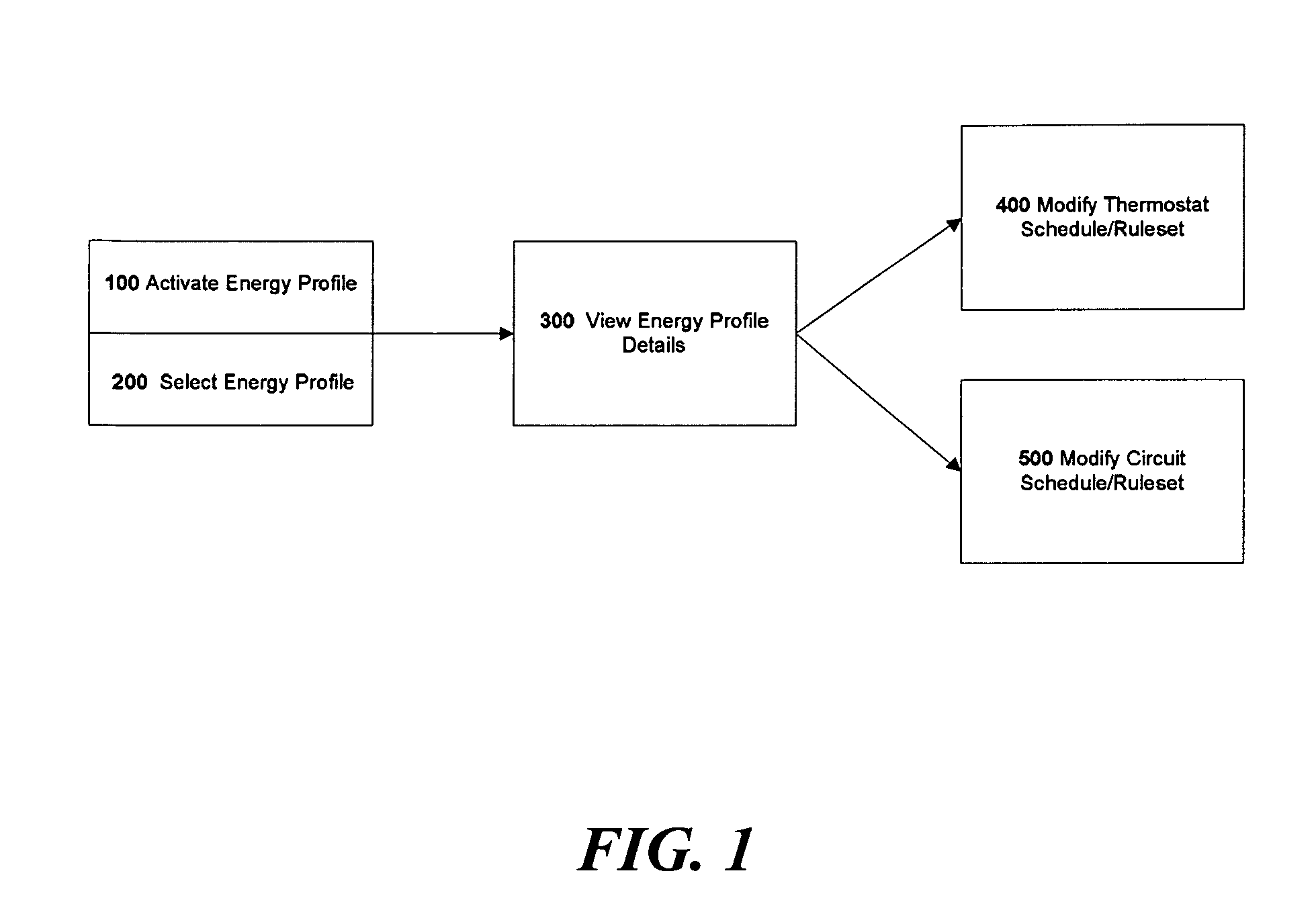
[0018]The present invention is described below with reference to block diagrams and operational illustrations of methods and devices to select and present media related to a specific topic. It is understood that each block of the block diagrams or operational illustrations, and combinations of blocks in the block diagrams or operational illustrations, can be implemented by means of analog or digital hardware and computer program instructions.

[0019]These computer program instructions can be provided to a processor of a general purpose computer, special purpose computer, ASIC, or other programmable data processing apparatus, such that the instructions, which execute via the processor of the computer or other programmable data processing apparatus, implements the functions / acts specified in the block diagrams or operational block or blocks.

[0020]In some alternate implementations, the functions / acts noted in the blocks can occur out of the order noted in the operational illustrations. F...


PUM


Abstract

A user interface is visibly displayed on a display device operatively connected to a first computer. The user interface enables an end user to enter at least one energy management rule for each of a plurality of electrical loads at a location, each rule including a command to be transmitted to the electrical load associated with the rule if a condition is met. The energy management rules for each of the plurality of electrical loads are received by a second computer. An energy management profile containing the energy management rules for each of the plurality of electrical loads at the location is created and stored using a second computer. The energy management profile is activated using the second computer. For each of the energy management rules where the condition has been met, the command associated with the rule is transmitted to the electrical load associated with the rule.

Description

[0001]This application claims priority to U.S. Provisional Patent Application No. 60 / 971,938 filed on Sep. 13, 2007, which is incorporated by reference in its entirety herein. This application relates to the subject matter of U.S. patent application Ser. No. 11 / 968,941 entitled “Utility Console for Controlling Aggregated Energy Resources” filed Jan. 3, 2008, which is incorporated herein by reference in its entirety.[0002]This application includes material which is subject to copyright protection. The copyright owner has no objection to the facsimile reproduction by anyone of the patent disclosure, as it appears in the Patent and Trademark Office files or records, but otherwise reserves all copyright rights whatsoever.FIELD OF THE INVENTION[0003]The present invention relates in general to the field of electric power, and in particular to graphical user interfaces for electric power management.BACKGROUND OF THE INVENTION[0004]The cost of electric power consumption represents a signifi...

Claims


Application Information

Patent Timeline
Patent Type & Authority Patents(United States)
IPC IPC(8): G06F1/26
CPCH02J3/14H02J13/0079H02J2003/146Y02B70/3225Y04S20/222Y04S20/224H02J2310/64H02J13/00028Y04S50/10
Inventor SHNEKENDORF, EDWARDMCMAHAN, COURTNEYFERGUSON, DOUGGOLDEN, BRIAN
Owner GRIDPOINT
Why Eureka
Try Eureka