Locking device for built pipe connections

a technology for locking devices and pipes, applied in the direction of pipe elements, couplings, screw threaded joints, etc., can solve the problem of high risk of injury, and achieve the effect of more safety and faster operation

Active Publication Date: 2011-02-15
NAT OIL WELL NORWAY
View PDF10 Cites 23 Cited by
  • Summary
  • Abstract
  • Description
  • Claims
  • Application Information

AI Technical Summary

Benefits of technology

[0012]It is an object for the present invention to provide a mechanical locking device for threaded pipe connections in drilling rigs which offers a secure locking without the use of flange connections.
[0014]A further object of the invention is to provide a locking device which can be operated more safely and faster than the flange arrangements that are currently in use.

Problems solved by technology

This causes a secure locking, but the installation and dismantling is time-consuming and the risk of injury is high.

Method used


Image

  • Locking device for built pipe connections
  • Locking device for built pipe connections
  • Locking device for built pipe connections

Examples


Embodiment Construction

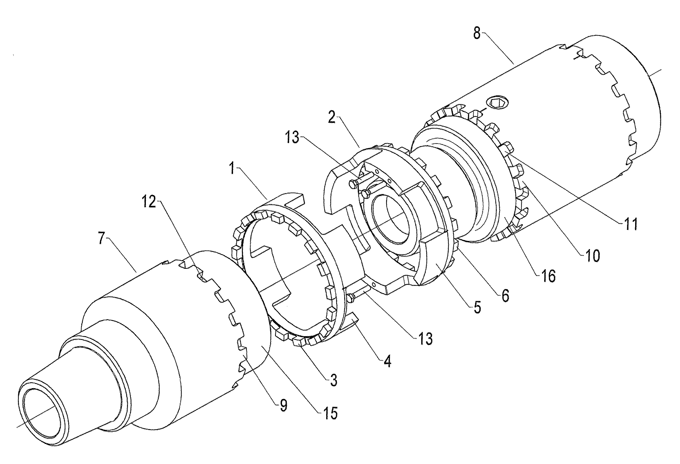
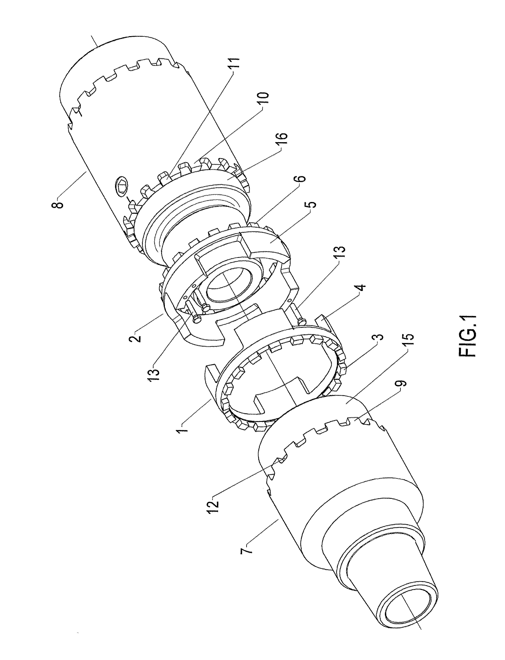
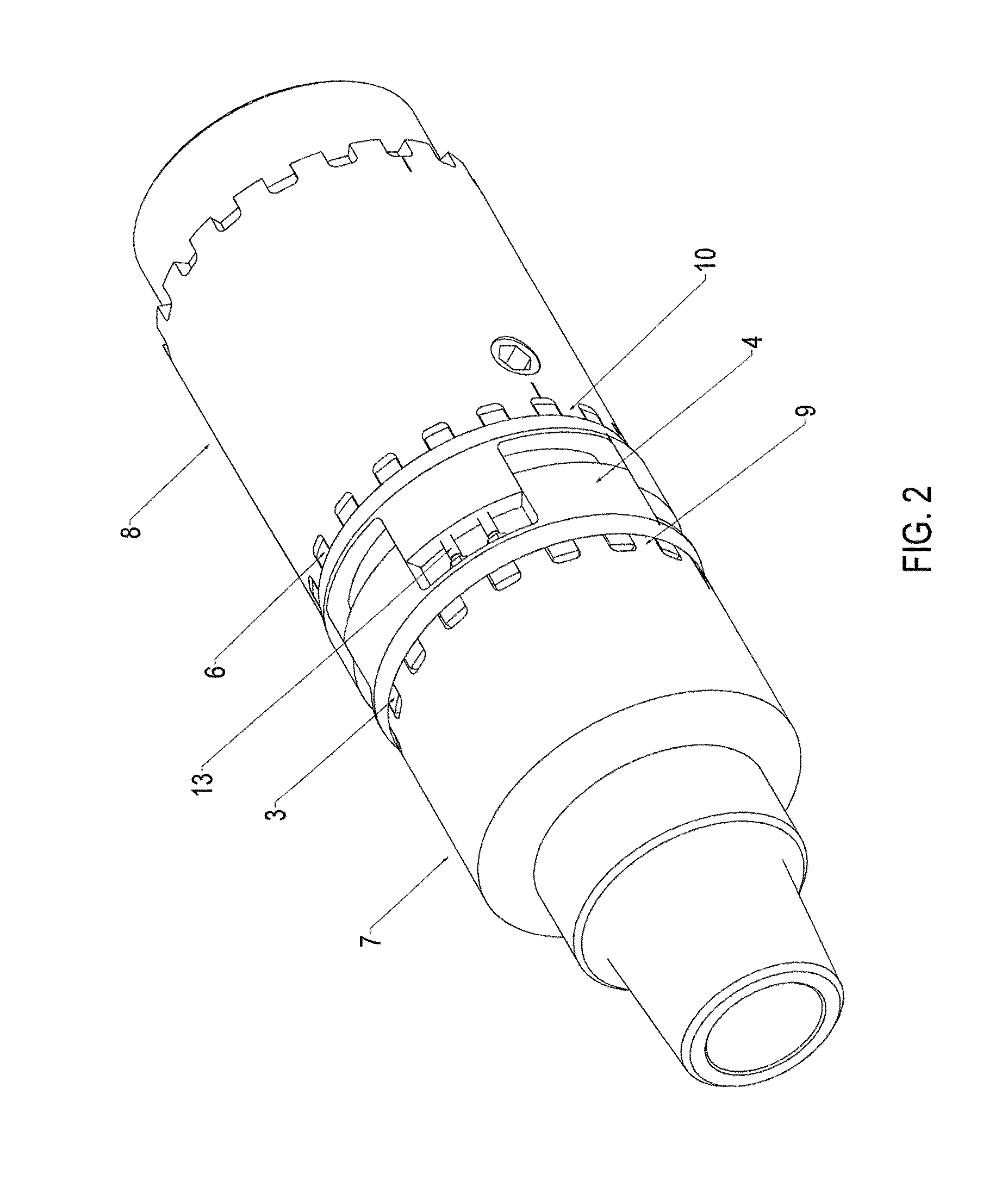
[0032]The invention comprises a device for locking threaded pipe connections for use on drill rigs. The locking arrangement comprises a first and a second ring 1, 2 with axial teeth 3, 4, 5, 6 and connection units 7, 8 with a number of notches and teeth 9, 10, 11, 12. The locking device is intended to secure the connection further, in addition to the momentum of torque applied according to present specifications, before the rings 1, 2 are positioned and locked.

[0033]Due to the number of teeth 3, 4, 5, 6 and the distribution of the teeth, the locking can be applied independently of the rotational position of the connection units 7, 8 with respect to each other after the threaded connection is completed. This is possible due to a different number of teeth 3, 6 on the first and second locking ring 1, 2 and their mutual positioning. The first 1 and second 2 ring have an even and odd number of teeth 3, 6, respectively, and a corresponding number of notches 12, 11 in the drilling machine / ...


PUM


Abstract

A locking device for locking a threaded pipe connection where two threaded connection units are screwed together. The locking device includes two locking rings which engage each other with corresponding teeth and notches on their first sides. Each of the two rings has a different number of teeth and notches on their second side. The two second sides, which face the connection units, are formed to engage a corresponding number of notches and teeth formed on the shoulder of the connection unit's opposite side, after the rings have been spread apart in an axial direction, while maintaining the engagement between the first and the second ring.

Description

[0001]The present invention concerns a mechanical locking device for built pipe connections used on drilling rigs.TECHNICAL BACKGROUND[0002]When drilling, a top drive or tower drill is used as drive unit for rotation and handling of the drill string when this is vertical in the centre of the well. The tower drill was introduced on the market around 1980 to replace the Kelly and rotary table, which up to that point had been the only available drive system. The main object of the tower drill is that the momentum of rotation is provided to the drill string at the top, instead of through a rotation pipe. The system can rotate and pump drilling mud continuously during drilling due to application of hydraulic or electric motors arranged above the pipe. The tower drill is frequently used on land-based rigs. The tower drill is connected to the top of the drill string directly via standard threads used in this industry.[0003]These connections comprise a male and a corresponding female thread...

Claims


Application Information

Patent Timeline
Patent Type & Authority Patents(United States)
IPC IPC(8): F16L15/00E21B17/043F16L15/08
CPCE21B17/043F16L15/08
Inventor AAS, BRYNJULV
Owner NAT OIL WELL NORWAY
Why Eureka
Try Eureka