System and methods for detecting turbulence based upon observations of light scintillation

a technology of light scintillation and system, applied in the field of system and technique for detecting turbulence in the atmosphere, can solve the problems of turbulence costing us airlines over $100 million per year in expense and loss of revenue, and poses a threat to aircraft damage,

Active Publication Date: 2011-02-15
THE BOEING CO
View PDF11 Cites 14 Cited by
  • Summary
  • Abstract
  • Description
  • Claims
  • Application Information

AI Technical Summary

Problems solved by technology

In addition to being uncomfortable for passengers, turbulence poses a threat of damage to aircraft, as well as a threat of injury to passengers and crew.
Indeed, the United States Federal Aviation Administration (FAA) presently requires that aircraft experiencing severe turbulence undergo inspection prior to returning to service, and at least one source has estimated that turbulence costs US airlines over $100 million per year in expense and lost revenue.
At present, turbulent air lying in the path of an aircraft is relatively difficult to identify.
Various turbulence detection systems based upon Doppler radar or lidar have met with some success, but these systems are generally based upon radio frequency reflections off of particulate matter in the air, so their use is limited at many cruising altitudes that are above cloud layers and that are relatively free of dust or other particulates.
Other systems that rely upon pilot reports (PIREPS) or automatic reporting from accelerometers on board existing aircraft can be beneficial as well, but these techniques are inherently unable to predict turbulence in areas where an aircraft has not previously experienced turbulent air.
These systems, while effective in many settings, are presently quite expensive, and they are not typically intended to detect close range turbulence (such as wake turbulence generated by other aircraft).

Method used


Image

  • System and methods for detecting turbulence based upon observations of light scintillation
  • System and methods for detecting turbulence based upon observations of light scintillation
  • System and methods for detecting turbulence based upon observations of light scintillation

Examples


Embodiment Construction

[0013]The following detailed description is merely exemplary in nature and is not intended to limit the described embodiments or the application and uses of the described embodiments. Furthermore, there is no intention to be bound by any expressed or implied theory presented in the preceding technical field, background, brief summary or the following detailed description.

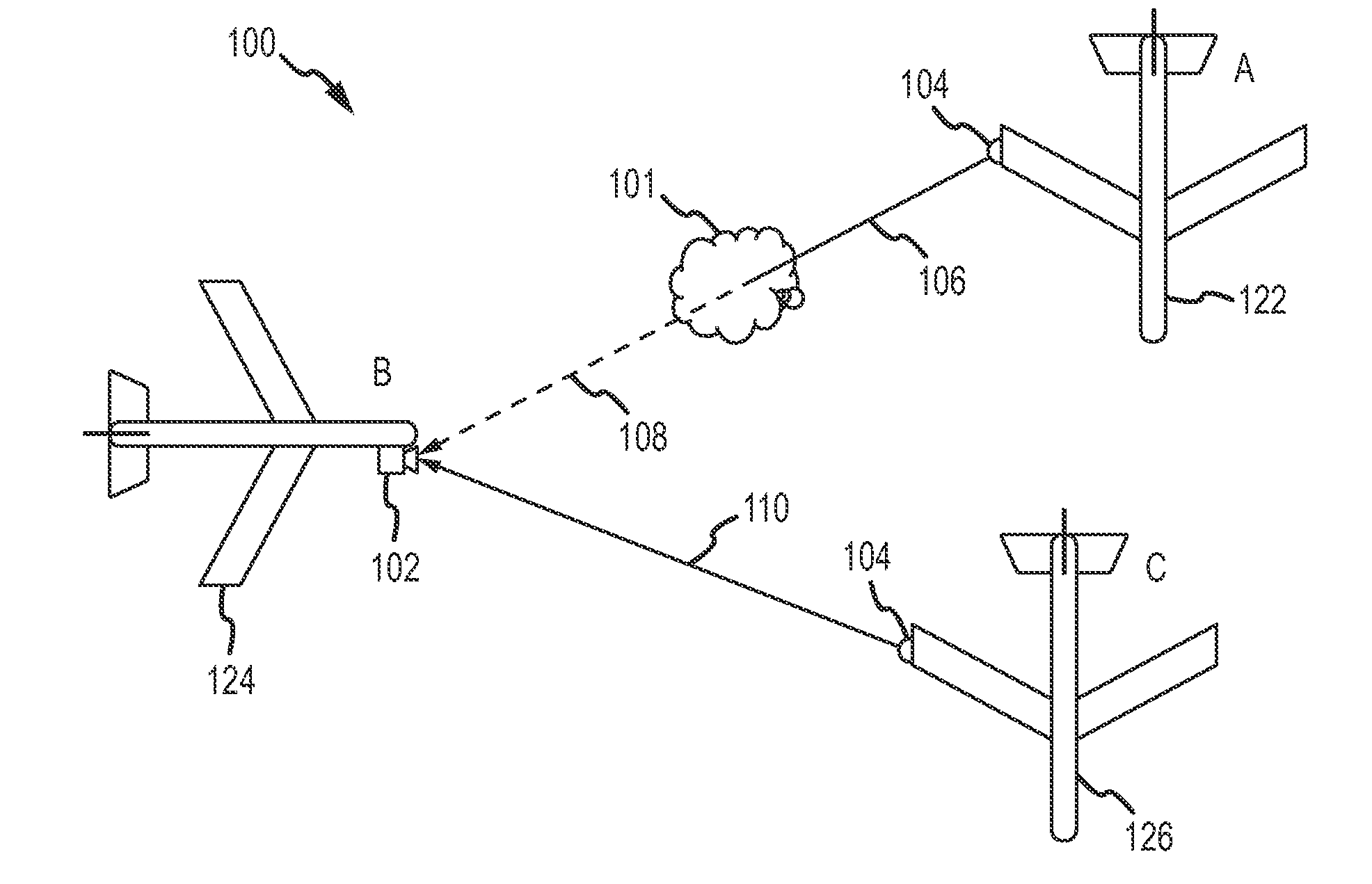
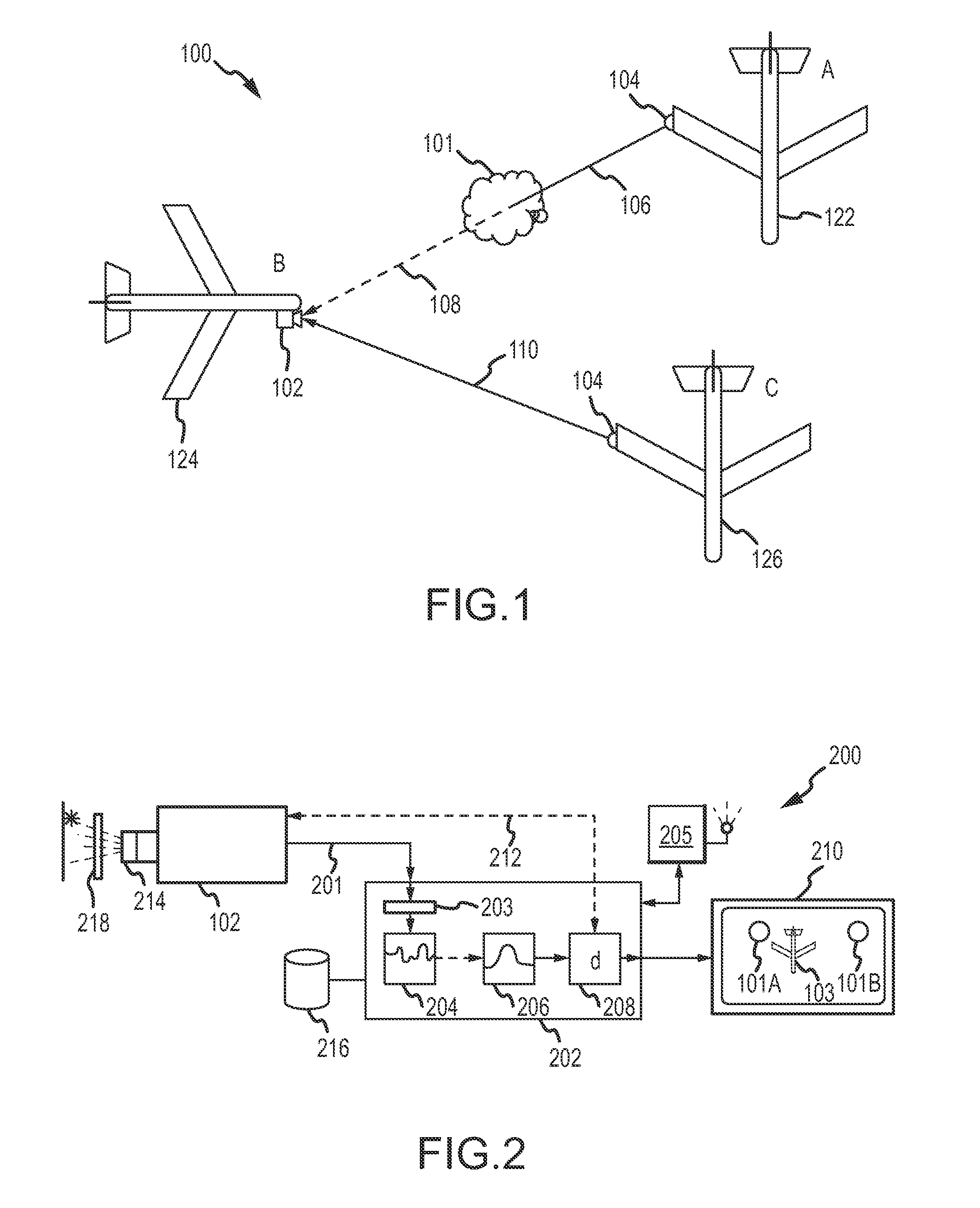
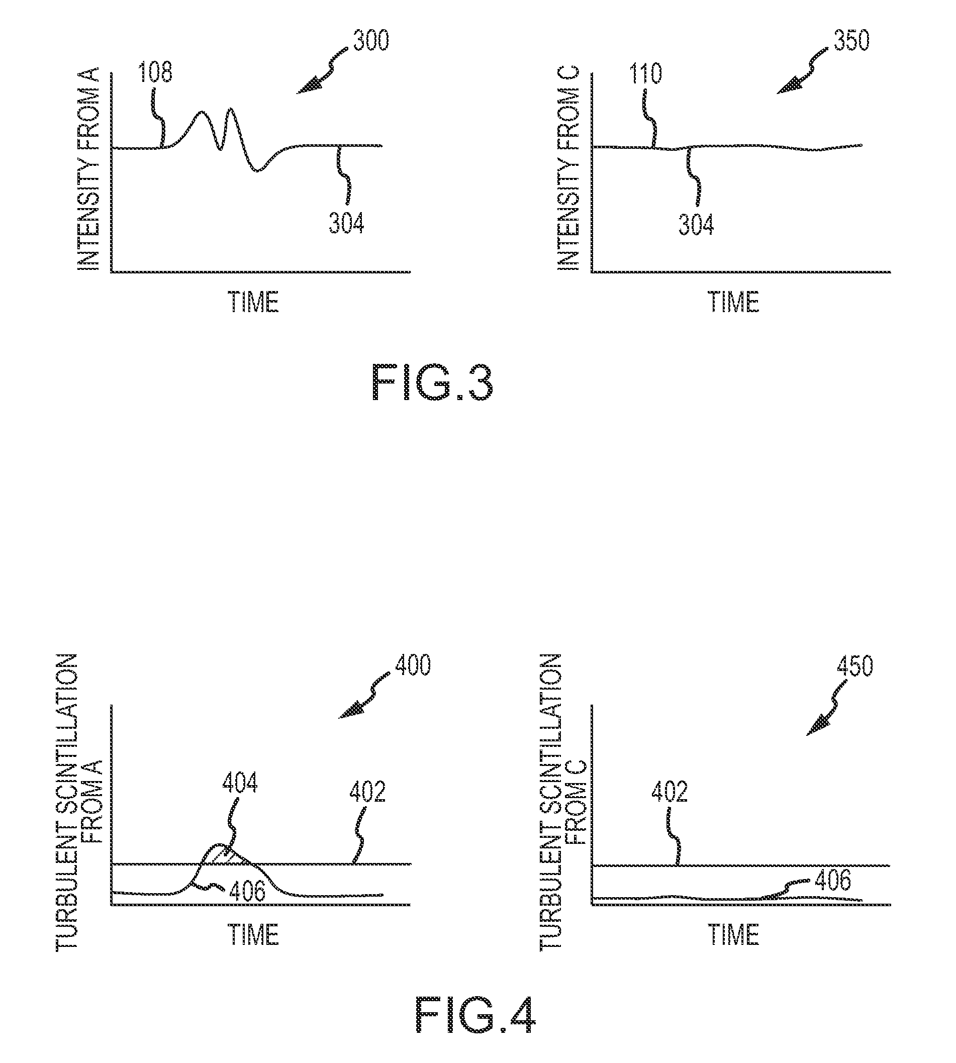
[0014]When light passes through the earth's atmosphere, differences in air density that can cause turbulence can also affect the amplitude and / or frequency of the light, thereby giving the light a scintillating appearance. Like stars “twinkling” in the night sky, lights observed though turbulent air have detectible scintillations that are generally not found in light passing though relatively calm air. By observing and quantifying this scintillation, then, turbulence can be remotely detected in clear air without the need for an aircraft to experience the turbulence firsthand. Further, because light has a relatively ...


PUM


Abstract

Systems and methods are provided for detecting turbulent air located between a light source and an observer based upon the scintillation of light produced by the light source. An optical sensor associated with the observer is configured to receive the light and to produce an indication of the light. A processor is configured to quantify scintillation in the light and to identify turbulent air between the light source and the optical sensor based upon the scintillation. A feedback device provides a notification when turbulent air is identified. Light sources and optical sensors may be located on airborne platforms or on the ground, and information may be transferred between multiple observers.

Description

TECHNICAL FIELD[0001]The embodiments described herein generally relate to systems and techniques for detecting turbulence in the atmosphere. More particularly, the embodiments described herein relate to detecting turbulence by observing the scintillation of light from remote light sources.BACKGROUND[0002]Most air travelers have experienced turbulence at some point during flight. In addition to being uncomfortable for passengers, turbulence poses a threat of damage to aircraft, as well as a threat of injury to passengers and crew. Indeed, the United States Federal Aviation Administration (FAA) presently requires that aircraft experiencing severe turbulence undergo inspection prior to returning to service, and at least one source has estimated that turbulence costs US airlines over $100 million per year in expense and lost revenue. Avoiding turbulence, then, has economic benefits in addition to the obvious benefits in terms of comfort and safety.[0003]At present, turbulent air lying i...

Claims


Application Information

Patent Timeline
Patent Type & Authority Patents(United States)
IPC IPC(8): G01P3/36
CPCG01P5/26G01W1/00G01P13/025G01W2001/003
Inventor TILLOTSON, BRIAN
Owner THE BOEING CO
Why Eureka
Try Eureka