PMSM rotor position detection device and method based on improved sliding-mode observer

A permanent magnet synchronous motor and rotor position detection technology, which is applied in motor control, electronic commutation motor control, electrical components, etc., can solve problems such as phase lag

Inactive Publication Date: 2017-11-10
BEIHANG UNIV
View PDF3 Cites 24 Cited by
  • Summary
  • Abstract
  • Description
  • Claims
  • Application Information

AI Technical Summary

Problems solved by technology

[0005] The technical problem to be solved by the present invention is: the purpose of the present invention is to overcome the phase lag problem caused when the low-pass filter is used to process the back EMF signal in the existing sliding mode observer, and consider the back

Method used


Image

  • PMSM rotor position detection device and method based on improved sliding-mode observer
  • PMSM rotor position detection device and method based on improved sliding-mode observer
  • PMSM rotor position detection device and method based on improved sliding-mode observer

Examples


specific Embodiment approach 1

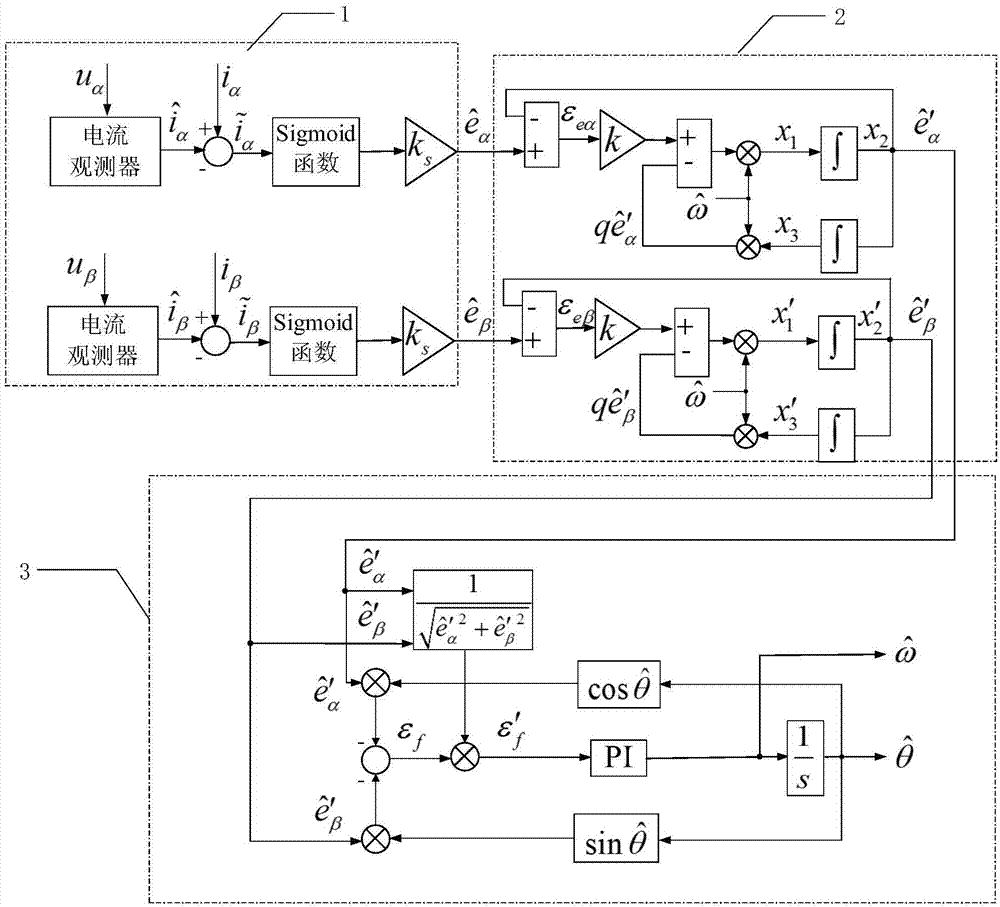
[0027] Specific implementation mode one: see figure 1 Describe this embodiment, the permanent magnet synchronous motor rotor position detection device based on the improved sliding mode observer described in this method includes a back EMF estimation part 1, a second-order generalized integral filter part 2 and a normalized quadrature phase-locked loop 3 .

[0028] The back EMF estimation part 1 is provided with four input terminals, which are respectively the α-axis voltage u in the two-phase stationary coordinate system α , β-axis voltage u β , α-axis current i α and β-axis current i β , set the two output terminals as the equivalent value of the back EMF of the α axis and the equivalent value of the back EMF of the β axis The second-order generalized integral filter part 2 sets the two input terminals as the equivalent value of the back EMF of the α axis and the equivalent value of the back EMF of the β axis Respectively with the back EMF equivalent value of the ...

specific Embodiment approach 2

[0029] Specific embodiment 2: This embodiment is a further limitation of the permanent magnet synchronous motor rotor position detection device based on the improved sliding mode observer described in specific embodiment 1. The back EMF estimation part 1 includes a current observer part, a sigmoid Function Section, Gain Section and Subtractor Section.

[0030] The setting of the back EMF estimation part 1 The four inputs are respectively the α-axis voltage u α Input and β-axis voltage u β Input, α-axis current i α and β-axis current i β . Among them, the current observer part sets the α-axis voltage u in the two-phase stationary coordinate system α Input and β-axis voltage u β input, sets the alpha axis to estimate the current output and beta-axis estimated current output. The output of the current detection part is used as the input of two subtractors, and the input of the subtractor also includes the α-axis current i α and β-axis current i β . α-axis current i ...

specific Embodiment approach 3

[0031] Specific embodiment three: this embodiment is a further limitation of the permanent magnet synchronous motor rotor position detection device based on the improved sliding mode observer described in specific embodiment one, and the second-order generalized integral filter part 2 includes four subtractors , two gain links, four multipliers and four integrators.

[0032] The input of the second-order generalized integral filter part 2 is connected with the output of the back EMF estimation part 1, that is, the input of the second-order generalized integral filter part 2 is the back EMF equivalent value of the α axis and the equivalent value of the back EMF of the β axis The equivalent value of the back EMF of the α axis As the input of the first subtractor of the alpha phase, and the other input of the first subtractor is the estimated value of the back EMF of the alpha axis Subtract, get α-axis back EMF error ε eα ;Equivalent value of the back EMF of the β axis A...


PUM


Abstract

The invention discloses a PMSM rotor position detection device and method based on an improved sliding-mode observer. A second-order generalized integration method is employed instead of a low pass filter to process a counterelectromotive force signal; an equivalent counterelectromotive force signal is observed through the improved sliding-mode observer based on a sigmoid function, buffeting of equivalent counterelectromotive force is inhibited through the second-order generalized integration method, phase lag caused by the low pass filter is avoided, a normalized quadrature phase locked loop is employed to estimate a rotor position signal according to the estimation counterelectromotive force signal, and the inhibition effect on each harmonic contained in the counterelectromotive force signal can be realized through resonance of the improved sliding-mode observer at the fundamental frequency. The method is advantaged in that the structure of the improved sliding-mode observer is simple, the observed counterelectromotive force signal is relatively accurate, and the high-precision rotor position information can be acquired.

Description

technical field [0001] The invention belongs to the technical field of motor control, and in particular relates to a permanent magnet synchronous motor rotor position detection device and method based on an improved sliding mode observer. Background technique [0002] The permanent magnet synchronous motor uses permanent magnets to provide excitation. Compared with the electric excitation motor, the loss of the excitation system is reduced, and the efficiency and power density of the motor are greatly improved. At the same time, it overcomes the unfavorable factors brought by DC motor brushes and commutators, and its application scope has rapidly developed from the initial military industry to aerospace, industrial automation and other fields. [0003] Due to the requirements of the drive system, permanent magnet synchronous motors are usually equipped with mechanical sensors to obtain rotor position information, such as Hall sensors, photoelectric encoders, etc. Although t...

Claims


Application Information

Patent Timeline
IPC IPC(8): H02P6/182H02P6/17
CPCH02P6/182H02P6/17H02P2207/05
Inventor 宋欣达康伟欣韩邦成郑世强刘刚毛琨
Owner BEIHANG UNIV
Why Eureka
Try Eureka