Eureka AIR delivers breakthrough ideas for toughest innovation challenges, trusted by R&D personnel around the world.

Design method for curve trajectory tracking controller

A tracking controller and design method technology, applied in the direction of adaptive control, general control system, control/regulation system, etc., can solve the problems of reducing system robustness, cumbersome processing flow, phase lag, etc., and achieve stable and accurate tracking , to avoid the cumbersome process, to avoid the effect of phase lag

Inactive Publication Date: 2018-11-06
FUZHOU UNIV
View PDF4 Cites 4 Cited by
  • Summary
  • Abstract
  • Description
  • Claims
  • Application Information

AI Technical Summary

Problems solved by technology

These fixed-point control schemes, if directly used to track a curved track signal, usually produce an obvious phase lag, and cannot achieve accurate track tracking
At present, there are mainly two processing methods in the tracking control of the curved trajectory: one is to use PID control, but the PID control algorithm needs to extract the differential signal for the error amount of trajectory tracking, which may cause noise amplification and reduce the robustness of the system; PID control cannot achieve fast response and low overshoot at the same time within a given bandwidth range, and is prone to the so-called integrator windup (Integrator windup)
The second way is to use segmented fitting control, which divides the curve track into a series of line segments, and then uses the existing point-to-point control technology for each line segment. The accuracy of track tracking not only depends on the fixed-point control technology adopted, but also It is related to the number of segments of the trajectory. The denser the segments, the higher the tracking accuracy may be, but the more cumbersome the entire processing flow

Method used


Image

  • Design method for curve trajectory tracking controller
  • Design method for curve trajectory tracking controller
  • Design method for curve trajectory tracking controller

Examples


Embodiment Construction

[0049] The present invention will be further described below in conjunction with the accompanying drawings and embodiments.

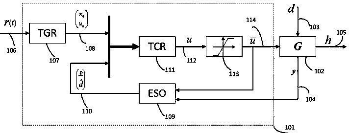
[0050] Please refer to figure 1 , the present invention provides a kind of design method of curve track tracking controller, it is characterized in that: comprise the following steps:

[0051] Step S1: Construct a trajectory generator according to the target trajectory signal, and generate a steady state value and an auxiliary control signal corresponding to the state vector of the servo system model;

[0052] Step S2: Incorporate the unknown disturbance of the system into the servo system model as an extended state quantity to obtain an augmented servo system model; design a reduced-order extended state observer based on the augmented servo system model to obtain the original state vector and unknown disturbance of the system estimated value of

[0053] Step S3: design the trajectory tracking control law according to the steady state value and the au...


PUM


Abstract

The invention relates to a design method for a curve trajectory tracking controller, in order to obtain accurate servo tracking performance and robustness. The method comprises steps of constructing atrajectory generator according to a target trajectory signal, and generating a steady state value and an auxiliary control signal corresponding to a state vector of a servo system model; integratingunknown disturbance as an extended state component of a system into the servo system model to obtain an augmented servo system model; according to the augmented servo system model, designing a reduced-order extended state observer to obtain an original state vector of the system and the estimated value of the unknown disturbance; according to the steady state value and the auxiliary control signalgenerated by the trajectory generator, designing a trajectory tracking control law; and according to the trajectory generator, the extended state observer, and the trajectory tracking control law, obtaining a trajectory tracking controller. The design method can realize smooth and accurate motion path tracking control of the servo mechanism such as the mechanical arm and the numerical control machine tool under the condition of unknown disturbance.

Description

technical field [0001] The invention and the field of industrial servo control specifically relate to a design method of a curve trajectory tracking controller. Background technique [0002] Fixed-point position adjustment and curve track tracking are the two most typical control problems in industrial servo systems. Usually, both fast response and low overshoot are required, and the static error in steady state should be as small as possible. So far, in the point-to-point position servo control system, domestic and foreign industrial circles and scientific research institutions have invested a lot of research and produced various control schemes. These fixed-point control schemes, if directly used to track a curved track signal, usually produce an obvious phase lag, and cannot achieve accurate track tracking. At present, there are mainly two processing methods in the tracking control of the curved trajectory: one is to use PID control, but the PID control algorithm needs t...

Claims


Application Information

Patent Timeline
Patent Type & Authority Applications(China)
IPC IPC(8): G05B13/04
CPCG05B13/042
Inventor 程国扬滕召海
Owner FUZHOU UNIV
Why Eureka
Eureka Blog
Learn More