Permanent magnet synchronous motor low-speed domain rotor position identification method

A permanent magnet synchronous motor, rotor position technology

Active Publication Date: 2019-11-08
JIANGSU UNIV
View PDF3 Cites 12 Cited by
  • Summary
  • Abstract
  • Description
  • Claims
  • Application Information

AI Technical Summary

Problems solved by technology

However, the traditional high-frequency signal injection methods, that is, the rotating voltage injection method and the pulse vibration voltage injection method, both need to use one or more filters in the process of current loop and signal demodulation, and the use of filters will bring different degrees of damage. Amplitude attenuation and phase lag will not only reduce the bandwidth of the current loop, affect the dynamic performance of the system, but also increase the position estimation error

Method used


Image

  • Permanent magnet synchronous motor low-speed domain rotor position identification method
  • Permanent magnet synchronous motor low-speed domain rotor position identification method
  • Permanent magnet synchronous motor low-speed domain rotor position identification method

Examples


Embodiment Construction

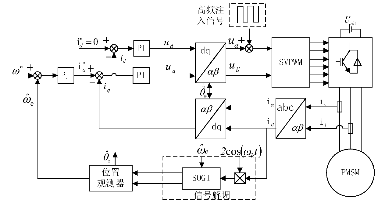
[0066] Based on the structural block diagram of the permanent magnet synchronous motor position sensorless control system of the present invention, as figure 1 shown. Among them, ω * For a given angular velocity value, is the angular velocity value estimated by the rotor position observer, is the given value of the d-axis current, is the given value of the q-axis current output by the speed regulator, u d , u q Respectively d, q axis voltage given value output by d, q axis current regulator, i d i q is d, q axis feedback current, i α i β is the α, β axis feedback current, u α , u β is the given value of the α and β axis voltage, SVPWM is the space voltage vector modulation module, i a i b is the sampled a, b phase stator current, U dc is the DC bus voltage of the inverter, PMSM is a permanent magnet synchronous motor, the signal demodulation part is realized by the content in step 2, and the position observer part is realized by the content in step 3. The spec...


PUM


Abstract

The invention discloses a permanent magnet synchronous motor low-speed domain rotor position identification method, so as to solve the problems that the traditional pulse signal injection method usesmultiple filters, the hysteresis effects are superimposed, the dynamic performance of the system is reduced, and the position estimation error is increased. A new low-speed position sensorless controlstrategy is proposed. In particular, on the basis of injection of a high-frequency pulse square wave voltage signal to a two-phase stationary coordinate system, through a generalized second-order integrator (SOGI), current in a beta axis is subjected to signal separation and amplitude demodulation, two paths of orthogonal signals including rotor position information are obtained, and through heterodyne and a rotor position observer, the rotor position information is extracted, and no filter is used during the whole signal demodulation process. The dynamic performance of the control system andthe accuracy of the rotor position estimation are effectively improved.

Description

technical field [0001] The invention relates to the field of permanent magnet synchronous motor control, in particular to a position sensorless rotor position identification method in the low speed field of permanent magnet synchronous motors. Background technique [0002] Permanent magnet synchronous motors are widely used in wind power generation, electric vehicles, aerospace and other fields due to their advantages of high power density, high efficiency and low noise. In order to achieve high-performance vector control, it is necessary to obtain accurate rotor position information. The rotor position can be accurately obtained by installing a high-resolution mechanical sensor, but it increases the size of the motor and hardware cost, and cannot be used in some special occasions. Therefore, it is of great significance to study the position sensorless control technology with high reliability and high precision to replace the mechanical sensor. [0003] For the control of t...

Claims


Application Information

Patent Timeline
IPC IPC(8): H02P21/18
CPCH02P2207/05H02P21/18
Inventor 刘国海胡顺沈跃刘慧
Owner JIANGSU UNIV
Why Eureka
Try Eureka