Feed-forward observer-based control for estimating cylinder air charge

a technology of observer-based control and cylinder air charge, which is applied in the direction of adaptive control, electric control, instruments, etc., can solve the problems of attenuation and delay of response, difficulty in accurately determining the precise quantity of air and fuel in the cylinder, and difficulty in precisely measuring and coordinating or synchronizing the air and fuel quantities which are actually combusted in the cylinder

Inactive Publication Date: 2004-04-13
FORD GLOBAL TECH LLC
View PDF13 Cites 26 Cited by
  • Summary
  • Abstract
  • Description
  • Claims
  • Application Information

AI Technical Summary

Benefits of technology

The present invention includes a number of advantages relative to prior art control strategies. For example, improved air charge estimation using the present invention allows more precise air / fuel ratio control. A priori knowledge of airflow control actuator position provides advanced notice via system modeling of how the cylinder air charge will be effected and allows improved air / fuel ratio control, especially during transient conditions. This may lead to reduced feedgas emissions and a corresponding reduction in the necessary size of the catalyst. A faster control system response without inducing instability or noise using the present invention may also result in improved driveability.

Problems solved by technology

However, due to various sensor limitations such-as response time and being located away from the combustion chamber of the cylinder, it is difficult to precisely measure and coordinate or synchronize the air and fuel quantities which are actually combusted in the cylinder.
The response characteristics of current MAF sensors coupled with the delay time associated with throttle valve positioning, transit time of the air mass between the MAF sensor and the cylinder, and response time of the fuel injector, make it difficult to accurately determine the precise quantity of air and fuel in the cylinder.
However, this method assumes air charge changes at a constant rate and does not compensate for airflow sensor filtering effects which lead to an attenuated and delayed response.

Method used


Image

  • Feed-forward observer-based control for estimating cylinder air charge
  • Feed-forward observer-based control for estimating cylinder air charge
  • Feed-forward observer-based control for estimating cylinder air charge

Examples


Embodiment Construction

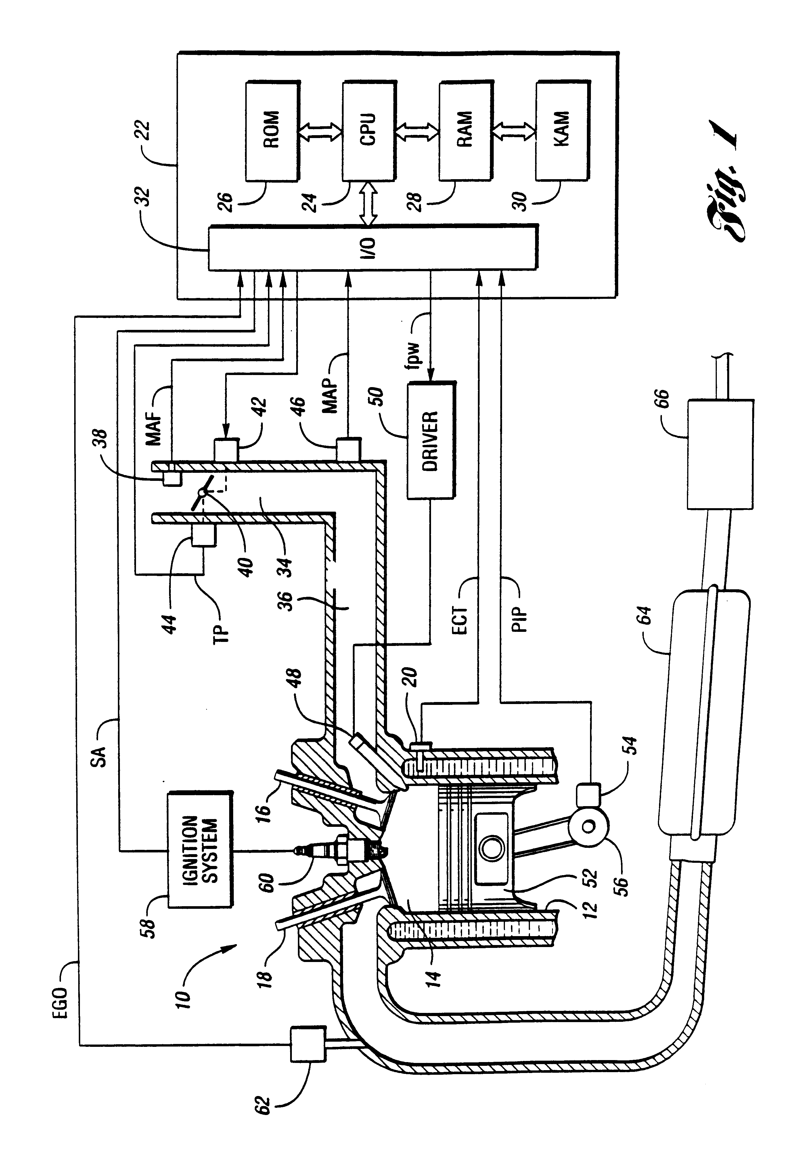
A block diagram illustrating one embodiment of an engine control system for an internal combustion engine according to the present invention is shown in FIG. 1. While a direct injection application is depicted in FIG. 1, the present invention is equally applicable to conventional port or throttle body injection systems as well. Similarly, while the present invention is described primarily with reference to an electronically controlled throttle to provide airflow control, the present invention may also be applied to various other types of airflow actuators such as cylinder intake / exhaust valves used in variable cam timing and variable valve timing applications with appropriate adjustments to the various models.

System 10 is preferably an internal combustion engine having a plurality of cylinders, represented by cylinder 12, having corresponding combustion chambers 14. As one of ordinary skill in the art will appreciate, system 10 includes various sensors and actuators to effect contro...


PUM


Abstract

A system and method for controlling an internal combustion engine to improve air / fuel ratio control using a feed-forward observer-based control strategy include estimating current and future airflow actuator positions, determining corresponding mass airflow values, and determining a future in-cylinder air charge based on a difference between the current and future mass airflow values. In one embodiment, the difference between current and future mass airflow estimates is used as a feed-forward term and combined with a sensed or measured value generated by a mass airflow sensor prior to being processed using a manifold filling model to predict the future cylinder air charge. In another embodiment, the current and future mass airflow estimates are processed using the manifold filling model with the results used to generate a future delta cylinder air charge that is subsequently used as a feed-forward term and combined with a measured air charge corresponding to a measured mass airflow processed by the manifold filling model.

Description

1. Technical FieldThe present invention relates to systems and methods for cylinder air charge estimation used in controlling an internal combustion engine.2. Background ArtPrecise air / fuel ratio control is an important factor in reducing feed gas emissions, increasing fuel economy, and improving driveability. Current internal combustion engine designs use various temperature, pressure, and flow sensors in an attempt to precisely control the amount of air and fuel, and thus the air / fuel ratio, for each cylinder firing event. However, due to various sensor limitations such-as response time and being located away from the combustion chamber of the cylinder, it is difficult to precisely measure and coordinate or synchronize the air and fuel quantities which are actually combusted in the cylinder. Acceptable control strategies have been developed to compensate for various sensor limitations under steady-state operating conditions. Effort is now being focused on improving these strategie...

Claims


Application Information

Patent Timeline
Patent Type & Authority Patents(United States)
IPC IPC(8): F02D41/14F02D41/18G05B13/04G05B17/02G05B17/00
CPCF02D41/1401F02D41/18G05B13/04G05B17/02F02D2041/141F02D2041/1416F02D2041/1433F02D2200/0402
Inventor SOLIMAN, IHAB S.PALLETT, TOBIAS JOHNROBICHAUX, JERRY D.
Owner FORD GLOBAL TECH LLC
Why Eureka
Try Eureka