Optical information recording-reproduction apparatus
a technology of optical information and recording equipment, which is applied in the direction of data recording, optical recording heads, instruments, etc., can solve the problems of affecting the stability of the servo control gap, affecting the affecting the speed of the approaching speed, etc., to achieve stable servo control of the gap, short time, and high speed approach
- Summary
- Abstract
- Description
- Claims
- Application Information
AI Technical Summary
Benefits of technology
Problems solved by technology
Method used
Image
Examples
first embodiment
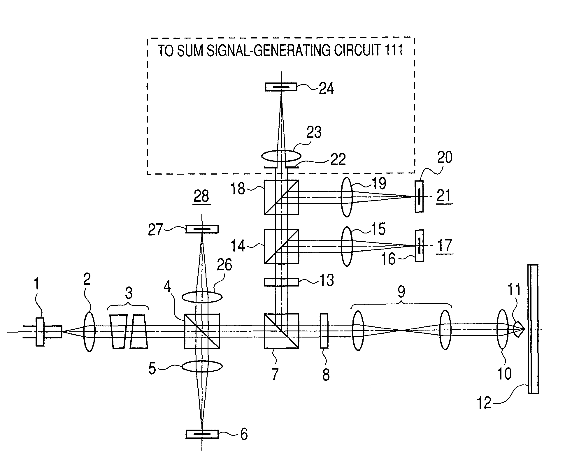
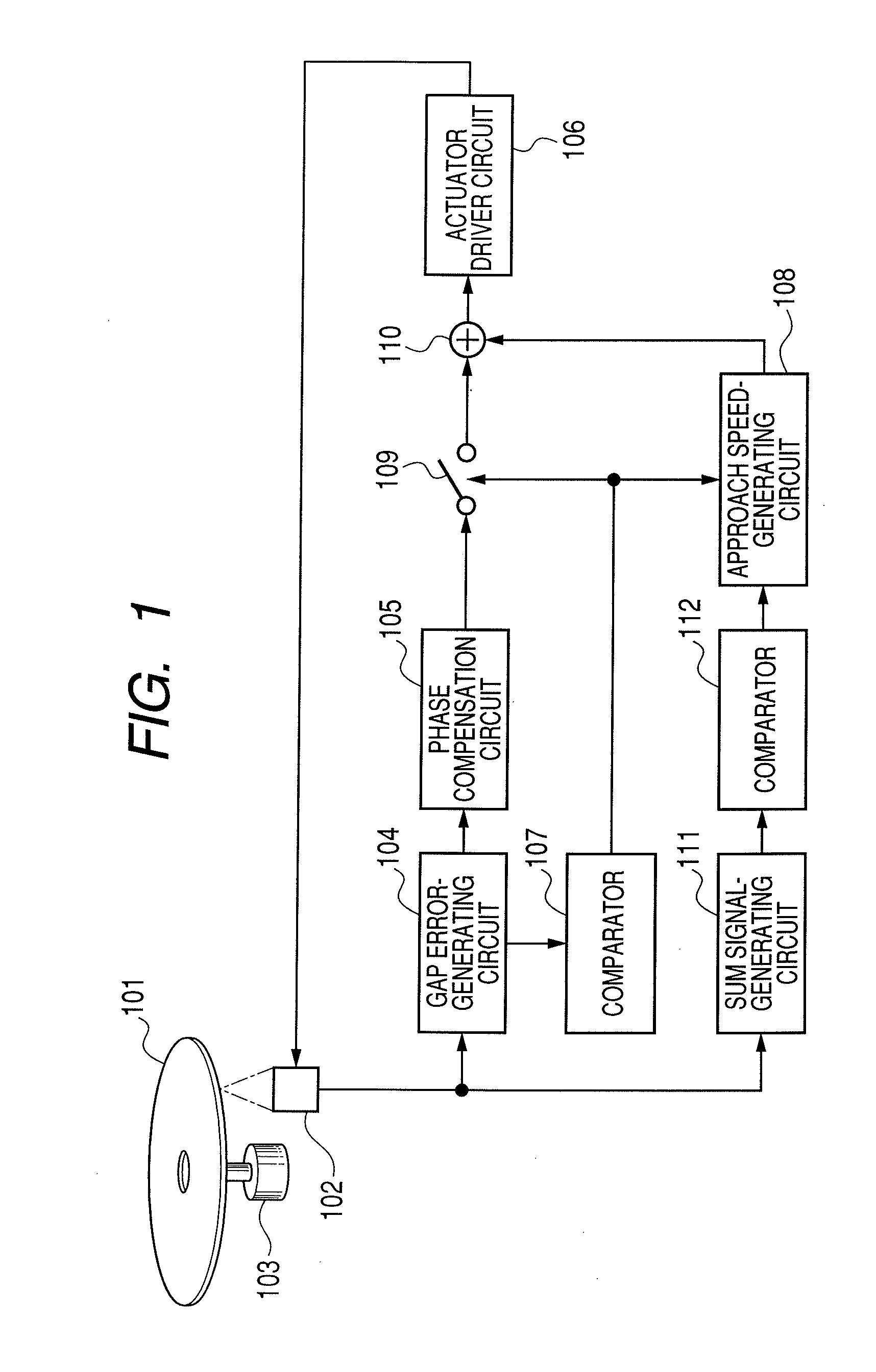
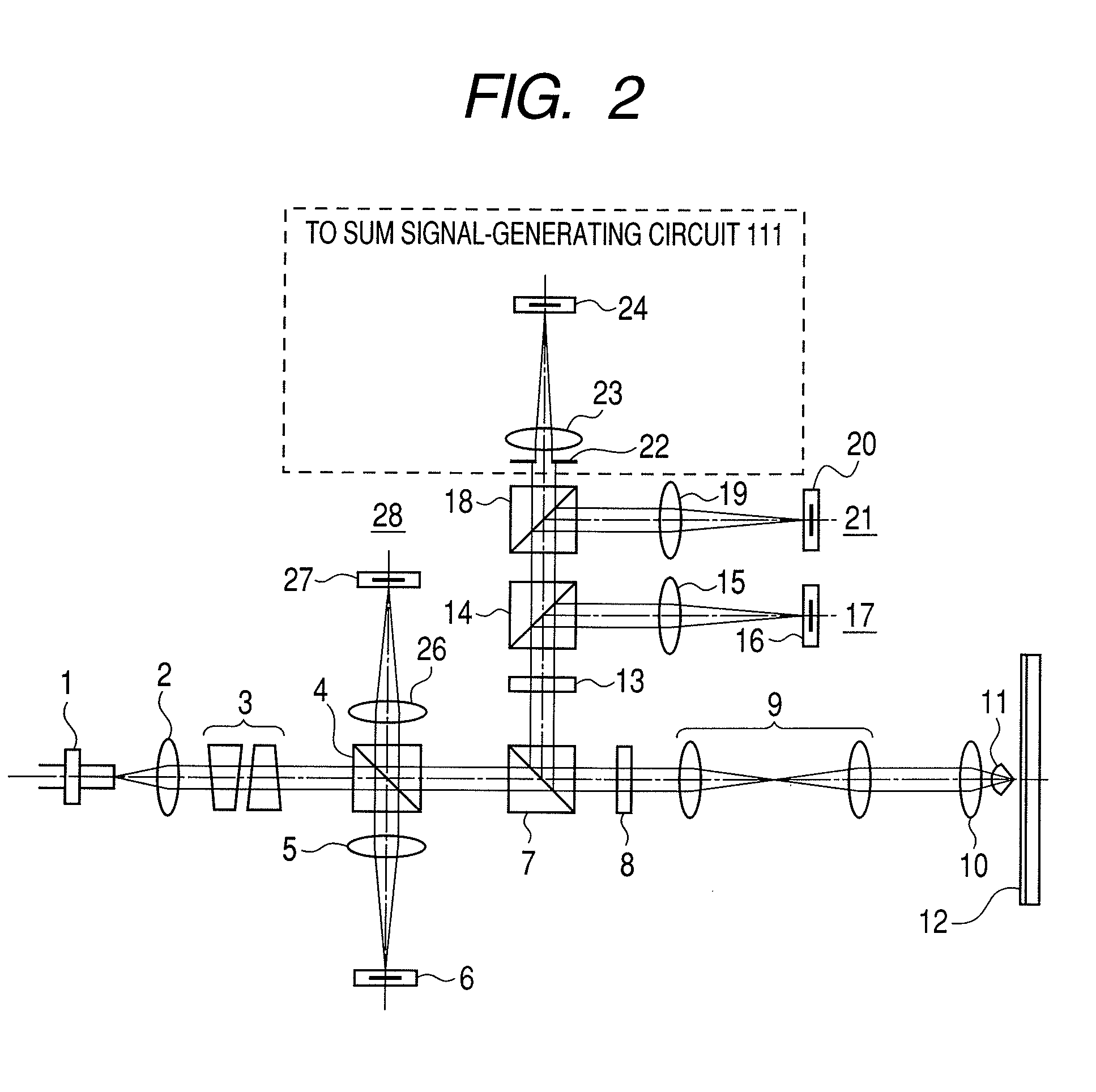
[0053]FIG. 1 is a block diagram of a First Embodiment of the optical information recording-reproduction apparatus of the present invention. In FIG. 1, the same symbols are used for denoting corresponding items as in FIG. 13, describing the prior art technique. FIG. 2 illustrates a constitution of the optical system (optical pickup of this Embodiment). FIG. 2 is different, in the portion surrounded by a broken line, from FIG. 13, illustrating the prior art.
[0054]The optical recording medium (optical disk 12) in FIG. 2 corresponds to optical disk 101 in FIG. 1. In FIG. 1, omitted are the circuit for recording information on the optical disk, the circuit for reproduction of information, the circuits for servo-control of focusing and tracking, and the circuit and mechanism for control of optical disk rotation. The same omission is also made in the Embodiment described later. (The focus servo circuit is not omitted in the drawings in the Embodiments described later.)
[0055]First, the cons...
second embodiment
[0068]FIG. 7 is a block diagram for a Second Embodiment of the present invention. In FIG. 7, the same symbols are used as in FIG. 1 for denoting corresponding members and items. FIG. 8 illustrates a constitution of the optical system (optical pickup) of this Embodiment. In FIG. 8, the same symbols are used as in FIG. 2 for denoting corresponding members. This Second Embodiment is different from the First Embodiment in that a focus error signal is generated together with a sum signal from the output from photodetector (PD4) 24, which receives the light beam of NA101, in FIG. 7, corresponds to optical disk 12 in FIG. 8.
[0069]Focus error-generating circuit 113 detects a focus error signal from the output from photodetector (PD4) 24. The focus error signal can be generated, for example, by use of a toric lens as sensor lens 23, and a four-division sensor as photodetector (PD4) 24, according to a conventional astigmatism method.
[0070]The light beam of NA101, enabling generation of the fo...
PUM
| Property | Measurement | Unit |
|---|---|---|
| wavelength | aaaaa | aaaaa |
| refractive index | aaaaa | aaaaa |
| thickness | aaaaa | aaaaa |
Abstract
Description
Claims
Application Information
 - R&D
- Intellectual Property
- Life Sciences
- Materials
- Tech Scout
- Unparalleled Data Quality
- Higher Quality Content
- 60% Fewer Hallucinations
Browse by: Latest US Patents, China's latest patents, Technical Efficacy Thesaurus, Application Domain, Technology Topic, Popular Technical Reports.
© 2025 PatSnap. All rights reserved.Legal|Privacy policy|Modern Slavery Act Transparency Statement|Sitemap|About US| Contact US: help@patsnap.com


