Optical disc device

Inactive Publication Date: 2014-02-06
HITACHI MEDIA ELECTORONICS CO LTD
View PDF2 Cites 0 Cited by
  • Summary
  • Abstract
  • Description
  • Claims
  • Application Information

AI Technical Summary

Benefits of technology

The patent describes a device that can correct color aberration without using an additional optical component. This device uses a specific objective lens that can cause color aberration when used with different types of optical discs. The device uses a special method to control the movement of the objective lens to minimize the amount of color aberration and ensure stable servo control during the recording process. The technical effect of this patent is the ability to use a single objective lens for different types of optical discs while ensuring better color accuracy and compatibility.

Problems solved by technology

When such a wavelength shift occurs, optical components of the optical pickup device suffer from a focus position change, that is, color aberration.
Particularly, the objective lens suffers from serious color aberration because it has a short focal distance and a small curvature radius.
Therefore, at an instant at which the optical disc device switches from the read mode to the write mode, the light beam suffers from color aberration due to a wavelength change.
If defocus occurs during a write, the servo may become unstable, resulting in the failure to perform a normal write operation.
However, an increase in the number of optical components not only decreases light transmittance, but also complicates an optical system, thereby causing a cost increase.
As a result, the amplitude of the tracking error signal (TES) deteriorates to destabilize a tracking servo.

Method used


Image

  • Optical disc device
  • Optical disc device
  • Optical disc device

Examples


first embodiment

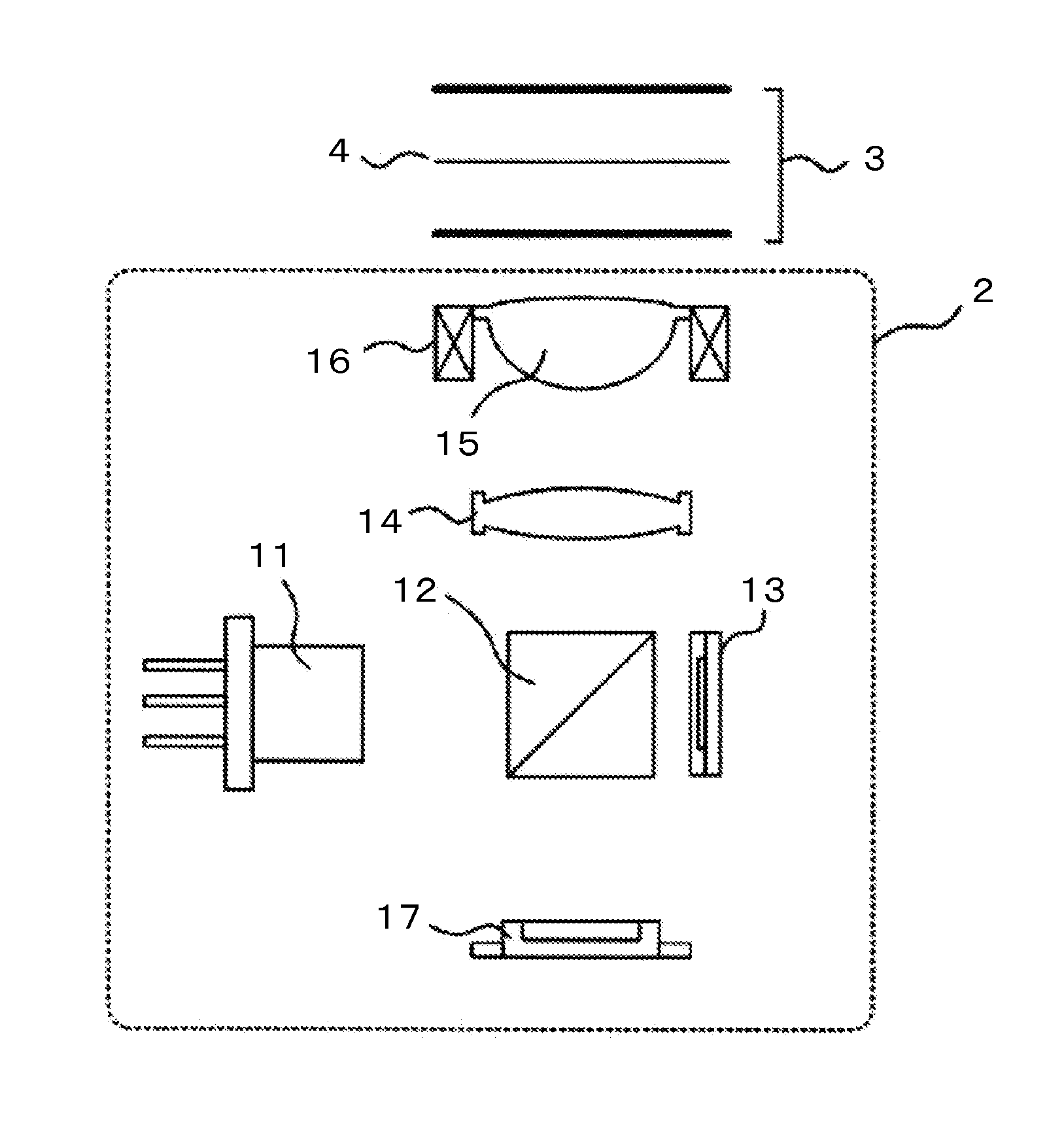
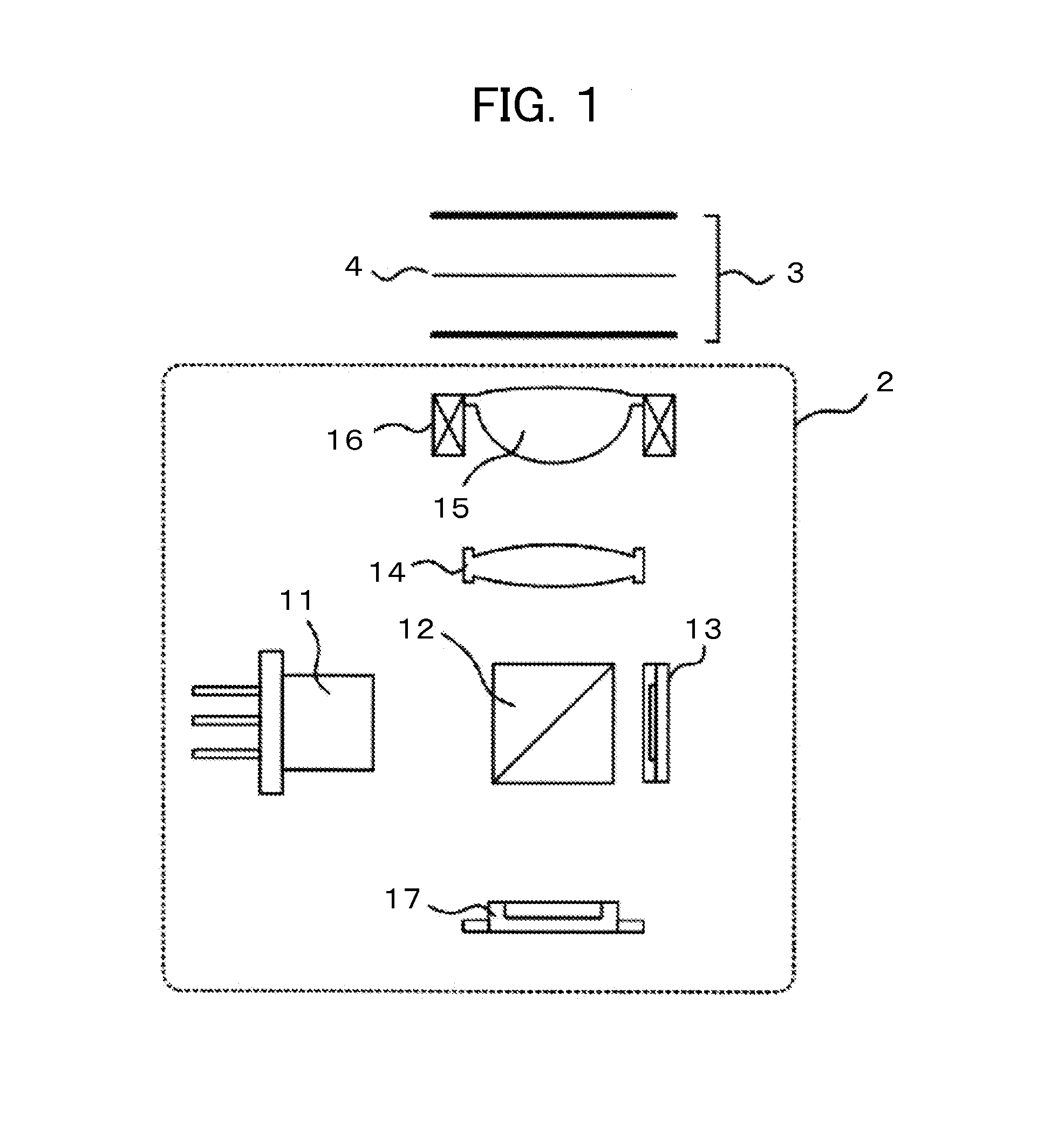
[0026]FIG. 1 is a configuration diagram illustrating an optical system of an optical pickup device 2 mounted in an optical disc device according to a first embodiment of the present invention. A laser light source 11 emits a light beam having a predetermined wavelength as divergent light. In general, the optical pickup device 2 uses a semiconductor laser as the laser light source 11. The light beam emitted from the laser light source 11 reflects from a beam splitter 12. The beam splitter 12 is an optical branching element that controls polarized light in such a manner as to transmit a linearly-polarized light oriented in a predetermined direction and reflect linearly-polarized light oriented in a direction orthogonal to the predetermined direction. Although FIG. 1 shows a prism as an example of the beam splitter 12, an optical branching element shaped, for instance, like a plane-polarization mirror may be used as the beam splitter 12.

[0027]A predetermined amount of light beam reflec...

second embodiment

[0068]A second embodiment of the present invention will now be described. The second embodiment differs from the first embodiment in the signal waveform representing the tracking signal gain correction amount for tracking control. The configurations of the optical pickup device and optical disc device are the same as described in conjunction with the first embodiment (FIGS. 1 and 3) and will not be redundantly described.

[0069]FIG. 6 is a diagram illustrating signal waveforms in the optical disc device that appear during a write operation according to the second embodiment. The signal waveforms shown in FIG. 6 are of the same type as shown in FIG. 4. Signal waveform (a) represents the write gate signal 40. Signal waveform (b) represents the defocus signal 41. Signal waveform (c) represents the focusing error signal 42. Signal waveform (d) represents the tracking signal gain correction amount 43. Signal waveform (e) represents the tracking error signal amplitude 44.

[0070]Operations pe...

third embodiment

[0078]A third embodiment of the present invention will now be described. When exercising tracking control, the third embodiment provides hold control of a tracking signal instead of correcting the gain of the tracking signal.

[0079]FIG. 7 is a block diagram illustrating the configuration of the optical disc device 1 according to the third embodiment. The present embodiment is characterized in that it includes a hold signal circuit 114 in place of the tracking signal gain control circuit 113 according to the first embodiment (FIG. 3). The hold signal circuit 114 is disposed between the control circuit 105 and the tracking control circuit 104. While a hold signal is ON, the hold signal circuit 114 holds the tracking error signal that is to be input from the servo signal generation circuit 101 to the tracking control circuit 104.

[0080]To correct color aberration, the control circuit 105 adds a predetermined defocus signal to the focusing error signal through the defocus application circ...


PUM


Abstract

Disclosed is an optical disc device that provides a stable servo signal with a simple configuration during the use of an objective lens showing significant color aberration. At time T0, which is before the start of a write operation (time T2), a defocus application circuit 111 generates a defocus signal DF1 to be added to a focusing error signal FES. A tracking signal gain control circuit 113 changes a tracking signal gain correction amount to be given to a tracking error signal TES to TG1. The defocus signal generated from the defocus application circuit terminates at substantially the same time the write operation starts (time T2). After the focusing error signal FES is no longer offset (at time T3), the tracking signal gain correction amount generated from the tracking signal gain control circuit 113 is restored to a reference value.

Description

CLAIM OF PRIORITY[0001]The present application claims priority from Japanese Patent Application Serial No. JP 2012-172131, filed on Aug. 2, 2012, the content of which is hereby incorporated by reference into this application.BACKGROUND OF THE INVENTION[0002](1) Field of the Invention[0003]The present invention relates to an optical disc device that provides stabilized servo control and performs a read or write operation from or to an optical disc.[0004](2) Description of the Related Art[0005]If the oscillation wavelength of a semiconductor laser changes to cause color aberration when the read or write operation from or to the optical disc is performed, a focusing servo becomes unstable.[0006]To address the above problem, an optical pickup device described in JP-A-2004-199768, which uses a blue-violet semiconductor laser and an objective lens made of high refractive index glass, is designed to not only reduce the amount of defocus even in the event of an instantaneous wavelength chan...

Claims


Application Information

Patent Timeline
IPC IPC(8): G11B7/1392
CPCG11B7/1392G11B7/0908G11B7/0945
Inventor NAGASAWA, MITSURUYAMAZAKI, KAZUYOSHIONOE, SHINSUKE
Owner HITACHI MEDIA ELECTORONICS CO LTD
Why Eureka
Try Eureka