Optical disc device

An optical disc device and a technology for optical discs, which are applied in the directions of beam guiding devices, optical recording heads, recording/reproducing by optical methods, etc., and can solve the problems of small defocusing amount and the like

Inactive Publication Date: 2014-02-12
HITACHI MEDIA ELECTORONICS CO LTD
View PDF5 Cites 1 Cited by
  • Summary
  • Abstract
  • Description
  • Claims
  • Application Information

AI Technical Summary

Problems solved by technology

[0003] Regarding this problem, the technical problem of Patent Document 1 is: "In an optical pickup device using a blue-violet semiconductor laser and an objective lens of high-refractive-index glass, in the case of an instantaneous wavelength change that cannot follow the focus, defocusing will also occur. The amount is suppressed to be small, and the spherical aberration caused by the change of the vibration wavelength of the light source accompanying the temperature change is corrected
[0004] In addition, the technical problem of Patent Document 2 is: "In an optical pickup for an optical recording apparatus, control the objective lens so as to remove the defocus shift due to the chromatic aberration caused by the wavelength change of the laser diode at the moment of switching from reproduction to recording. Effect, which corrects for the chromatic aberration that occurs when switching from reproduction mode to recording mode

Method used


Image

  • Optical disc device
  • Optical disc device
  • Optical disc device

Examples


Embodiment 1

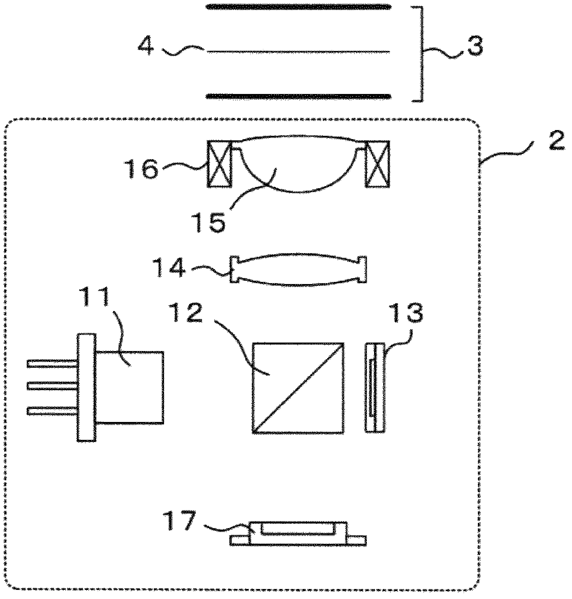
[0033] figure 1 It is a configuration diagram showing the optical system of the optical pickup device 2 mounted in the optical disc device of the first embodiment. The laser light source 11 emits a beam of predetermined wavelength in the form of divergent light. In addition, in the optical pickup device 2 , a semiconductor laser is generally used as the laser light source 11 . The light beam emitted from the laser light source 11 is reflected by a beam splitter (beam splitter) 12 . The beam splitter 12 is a beam splitting element that controls polarization so as to transmit linearly polarized light in a predetermined direction and reflect linearly polarized light in a direction perpendicular to the predetermined direction. figure 1 A prism is described as an example in , but a light beam splitting element in the shape of a polarizing plate mirror, for example, may also be used.

[0034] A beam of predetermined light quantity is reflected by the beam splitter 12 and enters a...

Embodiment 2

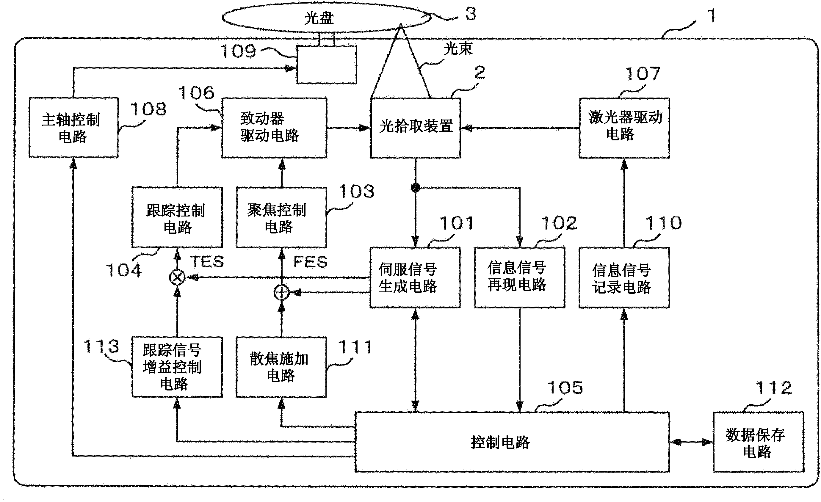
[0089]In the second embodiment, the signal waveform of the tracking signal gain correction amount of the tracking control is changed. Wherein, the structure of the optical pick-up device and the optical disc device is the same as that of embodiment 1 ( figure 1 , image 3 ) are the same, and their detailed descriptions are omitted.

[0090] Figure 6 It is a diagram explaining the signal waveform inside the device during the recording operation of the second embodiment. Types of each signal waveform and Figure 4 Same, (a) is optical gating signal 40, (b) is defocus signal 41, (c) is focus error signal 42, (d) is tracking signal gain correction amount 43, (e) is tracking error signal amplitude 44 .

[0091] The operation of this embodiment will be described with the passage of time. which, with Figure 4 Common descriptions are simplified.

[0092] In the playback state before time T0, the focus error signal (FES) 42 is 0 (zero), that is, it is at the in-focus position...

Embodiment 3

[0101] In the third embodiment, in the tracking control, instead of correcting the gain of the tracking signal, the tracking signal is held (held, made to wait) and controlled.

[0102] Figure 7 A block diagram showing the configuration of the optical disc device 1 according to the third embodiment. This embodiment is characterized in that instead of embodiment 1 ( image 3 ) tracking signal gain control circuit 113 , and a hold signal circuit 114 is provided between the control circuit 105 and the tracking control circuit 104 . The hold signal circuit 114 has a function of holding the tracking error signal input from the servo signal generating circuit 101 to the tracking control circuit 104 while the hold signal is ON.

[0103] In order to correct the chromatic aberration, the control circuit 105 adds a predetermined defocus signal to the focus error signal via the defocus application circuit 111 and inputs the same to the focus control circuit 103 just before the start o...


PUM


Abstract

Disclosed is an optical disc device that provides a stable servo signal with a simple configuration during the use of an objective lens showing significant color aberration. At time T0, which is before the start of a write operation (time T2), a defocus application circuit 111 generates a defocus signal DF1 to be added to a focusing error signal FES. A tracking signal gain control circuit 113 changes a tracking signal gain correction amount to be given to a tracking error signal TES to TG1. The defocus signal generated from the defocus application circuit terminates at substantially the same time the write operation starts (time T2). After the focusing error signal FES is no longer offset (at time T3), the tracking signal gain correction amount generated from the tracking signal gain control circuit 113 is restored to a reference value.

Description

technical field [0001] The present invention relates to an optical disc device that performs recording / reproducing operations on an optical disc by stabilizing servo control. Background technique [0002] When performing recording / reproducing operations on an optical disc, if the vibration wavelength of the semiconductor laser changes to cause chromatic aberration (chromatic aberration), there is a problem that the focus servo is unstable. [0003] Regarding this problem, the technical problem of Patent Document 1 is: "In an optical pickup device using a blue-violet semiconductor laser and an objective lens of high-refractive-index glass, in the case of an instantaneous wavelength change that cannot follow the focus, defocusing will occur. The amount is suppressed to be small, and the spherical aberration caused by the change of the vibration wavelength of the light source accompanying the temperature change is corrected." As the solution, it is described: "The diffraction p...

Claims


Application Information

Patent Timeline
Patent Type & Authority Applications(China)
IPC IPC(8): G11B7/135G11B7/1374
CPCG11B7/1392G11B7/0908G11B7/0945
Inventor 永泽充山崎和良尾上慎介
Owner HITACHI MEDIA ELECTORONICS CO LTD
Why Eureka
Try Eureka