Method of processing defect detection signal in recording and/or reproducing apparatus that records and/or reproduces optical information storage medium

a technology of optical information storage medium and defect detection signal, which is applied in the direction of digital signal error detection/correction, data recording, instruments, etc., can solve the problems of optical disk recording and/or reproducing apparatus, optical disk storage medium use, and easy occurrence of physical defects, etc., to achieve stable servo control

Inactive Publication Date: 2008-03-20
SAMSUNG ELECTRONICS CO LTD
View PDF4 Cites 1 Cited by
  • Summary
  • Abstract
  • Description
  • Claims
  • Application Information

AI Technical Summary

Benefits of technology

[0014]According to an aspect of the invention there is provided a method of changing a defect detection signal to enable stable servo control when a defect is detected in an optical disk recording and / or reproducing apparatus.

Problems solved by technology

When an optical disk storage medium is not housed in a cartridge, various physical defects may easily occur during the use of the optical disk storage medium as compared to when the optical disk storage medium is housed in a cartridge.
Such defects include, for example, a scratch, a fingerprint, a water drop mark, a black dot, a pin-hole like defect through which a laser beam is transmitted, and a defect which may occur during a disk manufacturing process and indicates that a portion of a data surface on which data is recorded is missing.
In particular, during an optical disk coating process, a bubble defect due to absorption of an air bubble on a disk surface may occur.
These defects significantly affect an optical disk recording and / or reproducing apparatus since signal reproduction after a defect is impossible or hindered due to distortion or omission of a reproduced signal or malfunction of a servo signal required for the signal reproduction.
If the defect zone is large enough to cause the defect detection period to exceed a certain time that depends on characteristics of the recording and / or reproducing apparatus and the optical disk, the servo control will be in a very unstable state by the time the defect detection signal returns to the servo on state, resulting in incorrect tracking.
That is, since a servo on period between the two servo hold periods is very short, servo control during the servo on period is very unstable, resulting in a tracking failure and an Error Correction Code (ECC) error, and since an angle of a bubble defect varies according to a size of the bubble defect, tracking of a correct track is impossible, resulting in a tracking error.
As described above, if the defect detection signal shown in FIGS. 1A or 1B is generated, servo control is unstable at a time when a defect zone starts, and a servo on signal is more unstable at a time when a servo hold signal ends, resulting in an incorrect optical focus and incorrect tracking.

Method used


Image

  • Method of processing defect detection signal in recording and/or reproducing apparatus that records and/or reproduces optical information storage medium
  • Method of processing defect detection signal in recording and/or reproducing apparatus that records and/or reproduces optical information storage medium
  • Method of processing defect detection signal in recording and/or reproducing apparatus that records and/or reproduces optical information storage medium

Examples


Embodiment Construction

[0032]Reference will now be made in detail to embodiments of the invention, examples of which are shown in the accompanying drawings, wherein reference numerals refer to like elements throughout. The embodiments are described below in order to explain the invention by referring to the figures.

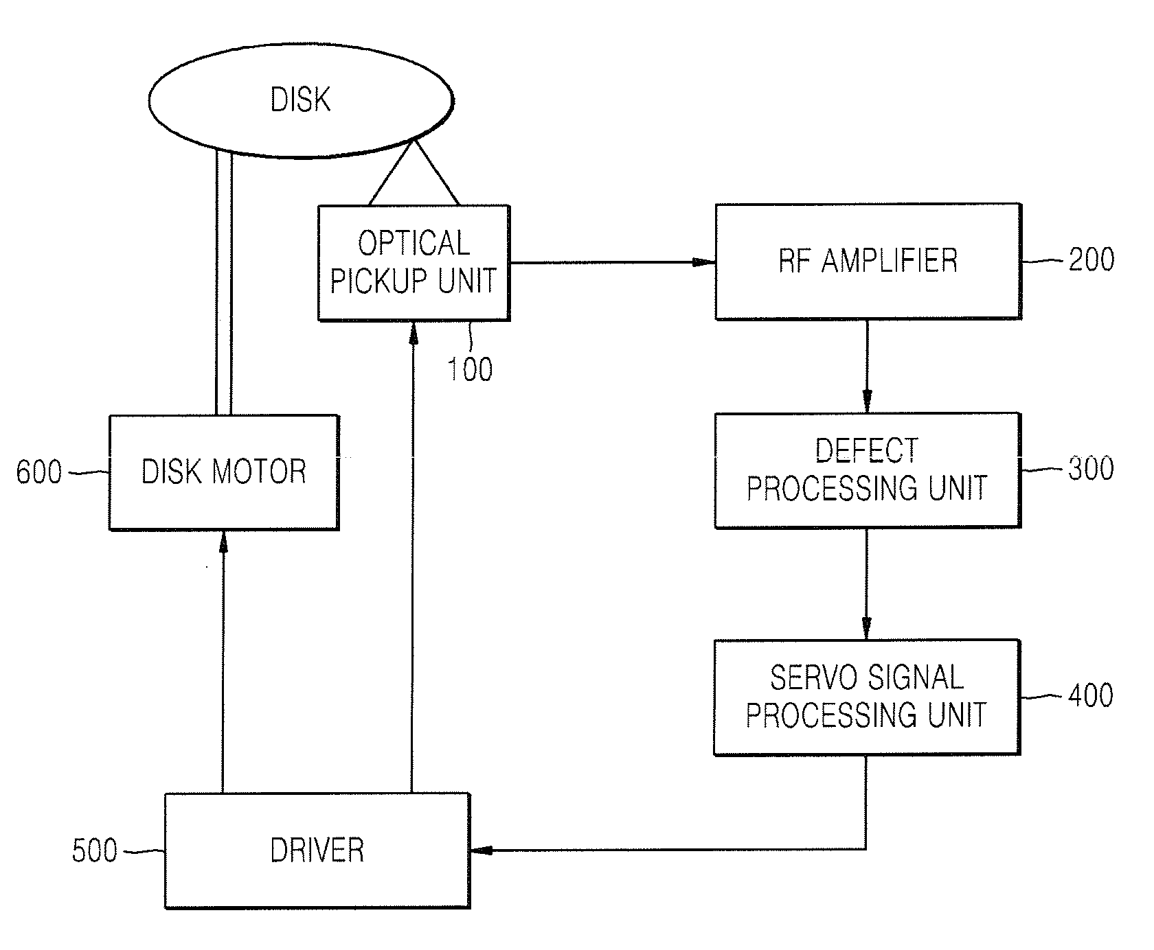
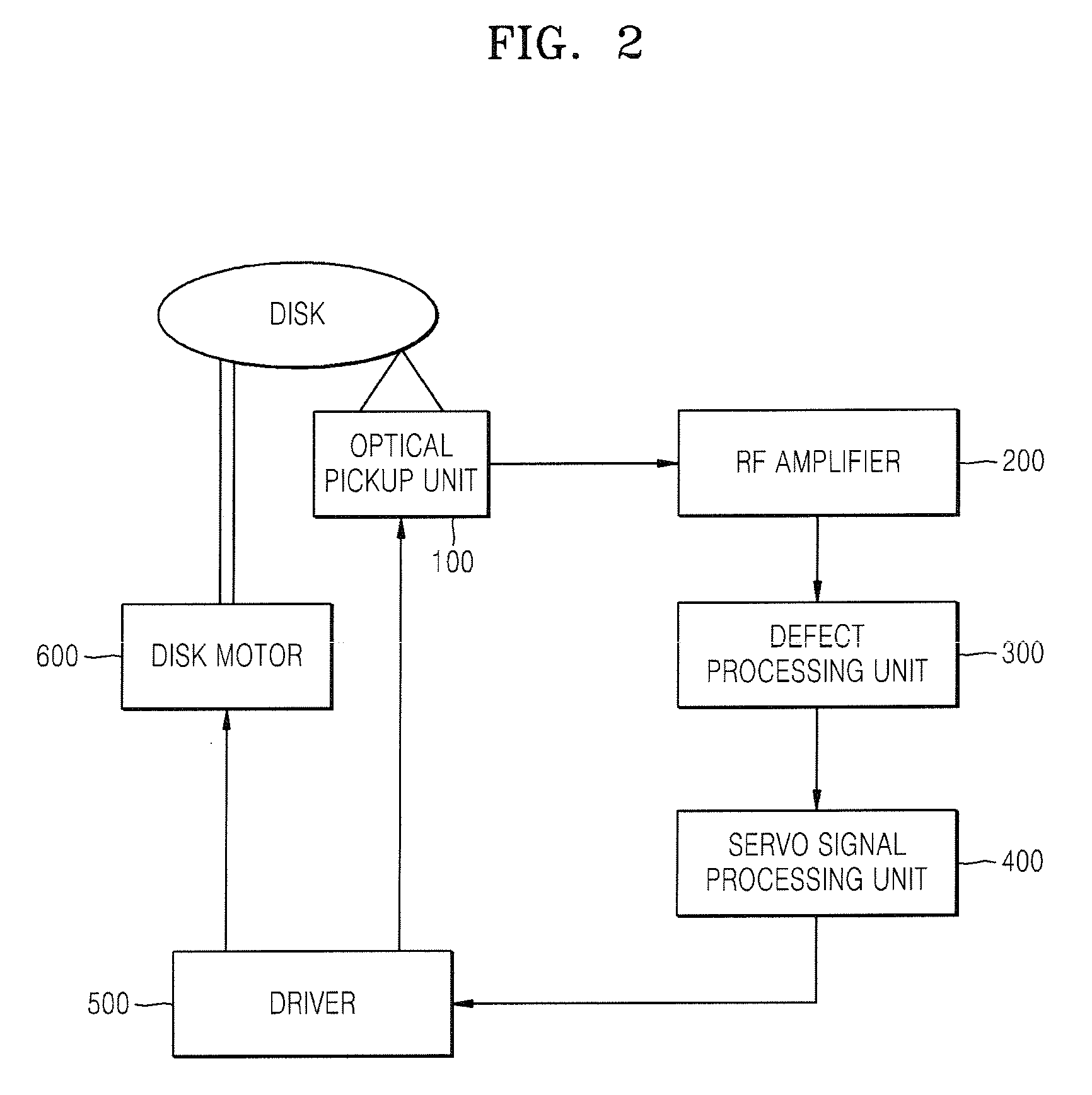
[0033]FIG. 2 is a block diagram of an optical disk recording and / or reproducing apparatus according to an aspect of the invention.

[0034]Referring to FIG. 2, the optical disk recording and / or reproducing apparatus includes an optical pickup unit 100, a radio frequency (RF) amplifier 200, a defect processing unit 300, a servo signal processing unit 400, a driver 500, and a disk motor 600.

[0035]The optical pickup unit 100 includes a tracking actuator (not shown) for tracking servo control and a focusing actuator (not shown) for focus servo control, and generates an electrical RF signal by optically picking up information recorded on a disk.

[0036]The RF amplifier 200 amplifies the RF signal output ...


PUM

PropertyMeasurementUnit
radio frequencyaaaaaaaaaa
defectaaaaaaaaaa
widthaaaaaaaaaa

Abstract

A method of processing a defect detection signal in a recording and/or reproducing apparatus that records and/or reproduces an optical information storage medium the method including generating a defect detection signal comprising a servo hold pulse from a radio frequency (RF) signal output from an optical pickup unit; and generating an OR signal by performing an OR operation on the defect detection signal and a first pulse signal having a first pulse width. The method further includes generating an AND signal by performing an AND operation on the OR signal and a second pulse signal having a second pulse width.

Description

CROSS-REFERENCE TO RELATED APPLICATIONS[0001]This application claims the benefit of Korean Patent Application No. 2006-89247 filed on Sep. 14, 2006, in the Korean Intellectual Property Office, the disclosure of which is incorporated herein by reference in its entirety.BACKGROUND OF THE INVENTION[0002]1. Field of the Invention[0003]An aspect of the invention relates to a defect detection signal of a recording and / or reproducing apparatus that records and / or reproduces an optical information storage medium, and more particularly to a method of processing a defect detection signal of an optical disk. The term “recording and / or reproducing apparatus” refers to an apparatus that record, or an apparatus that can reproduce, or an apparatus that can both record and reproduce.[0004]2. Description of the Related Art[0005]An optical disk recording and / or reproducing apparatus is widely used record and / or reproduce multimedia data, such as audio / video data and other digital data, because of a r...

Claims


Application Information

Patent Timeline
Patent Type & Authority Applications(United States)
IPC IPC(8): G11B7/00
CPCG11B7/00375G11B7/0901G11B2220/2537G11B7/0953G11B2020/1281G11B7/0948G11B20/18G11B7/09G11B20/10
Inventor SHIN, JONG-HYUNOTSUKA, TATSUHIROKIM, KWAN-JOONPARK, YOUNG-JAE
Owner SAMSUNG ELECTRONICS CO LTD
Why Eureka
Try Eureka