Optical information recording-reproduction apparatus

a technology of optical information and recording equipment, which is applied in the direction of data recording, optical recording heads, instruments, etc., can solve the problems of long servo control time, damage to the sil and the optical disk, and inapplicability, etc., and achieve stable servo control of the gap, short time, and high speed approach

Inactive Publication Date: 2008-08-21
CANON KK
View PDF6 Cites 22 Cited by
  • Summary
  • Abstract
  • Description
  • Claims
  • Application Information

AI Technical Summary

Benefits of technology

[0031]The present invention intends to provide an optical recording-reproduction apparatus, which enables a high speed approach of the SIL to the optical recording medium without collision of the SIL against the optical recording medium by stable servo-control of the gap in a short time.

Problems solved by technology

The overshoot of more than 100 nm will cause collision of the SIL against the optical disk to damage the SIL and the optical disk.
However, the lower approaching speed requires a longer time for the servo-control, and is not desirable practically.
Therefore, overshoot of 100 nm or more will cause collision of the SIL against the optical disk, disadvantageously.

Method used


Image

  • Optical information recording-reproduction apparatus
  • Optical information recording-reproduction apparatus
  • Optical information recording-reproduction apparatus

Examples


first embodiment

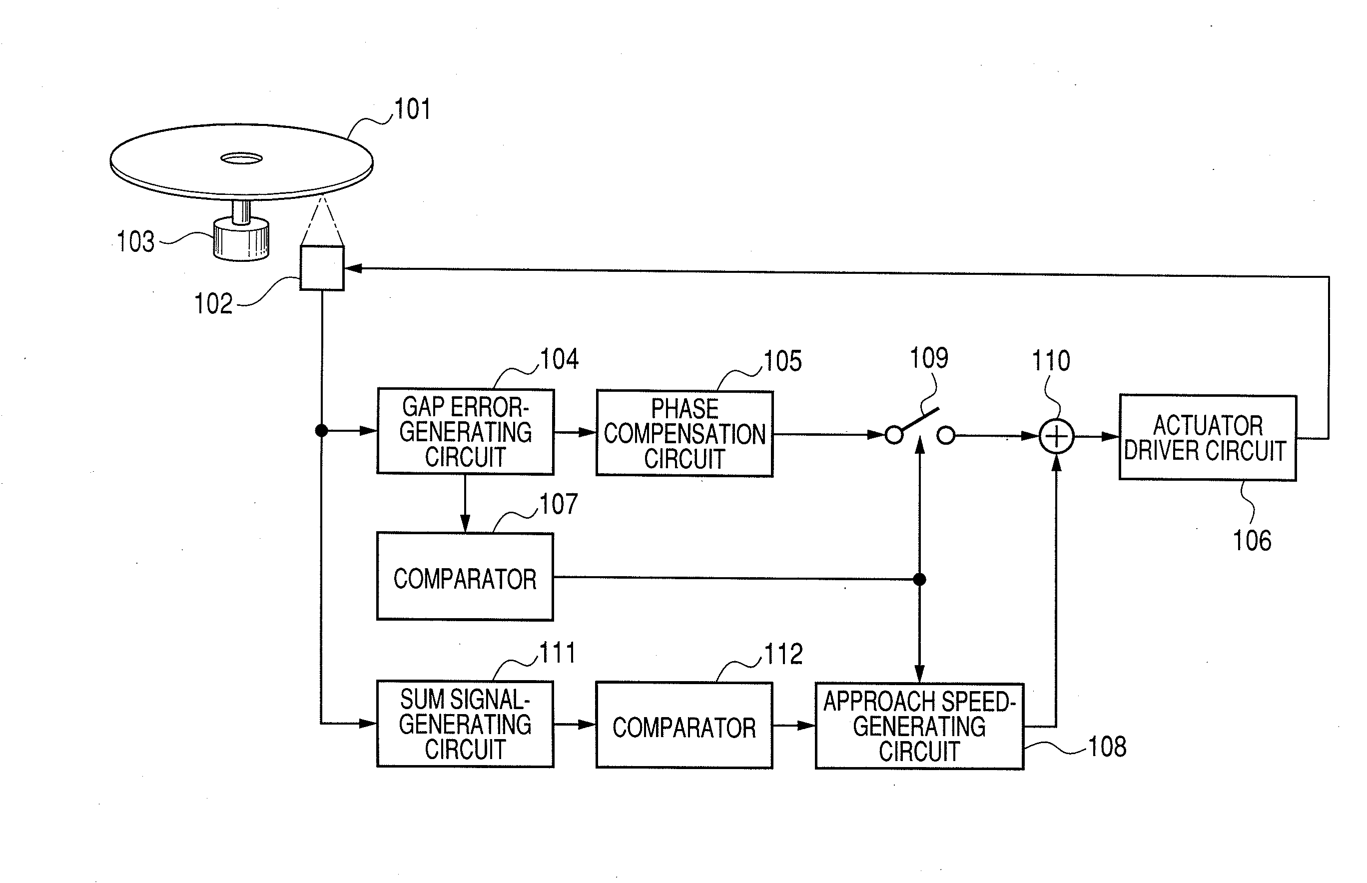
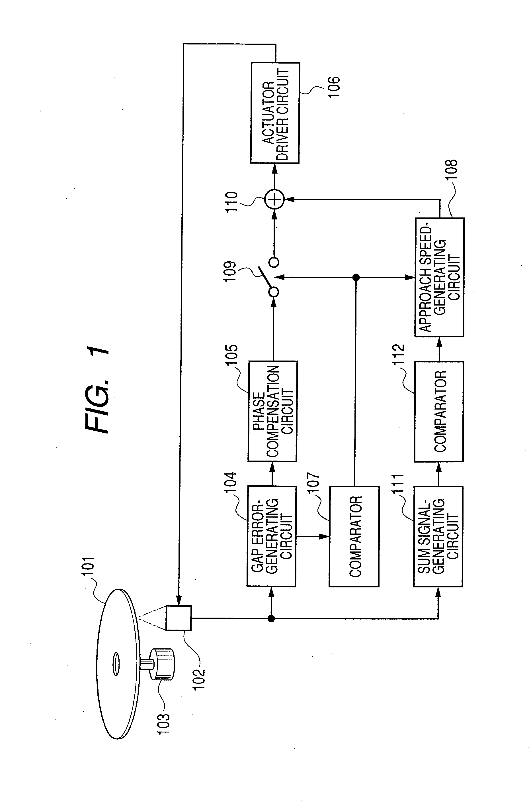
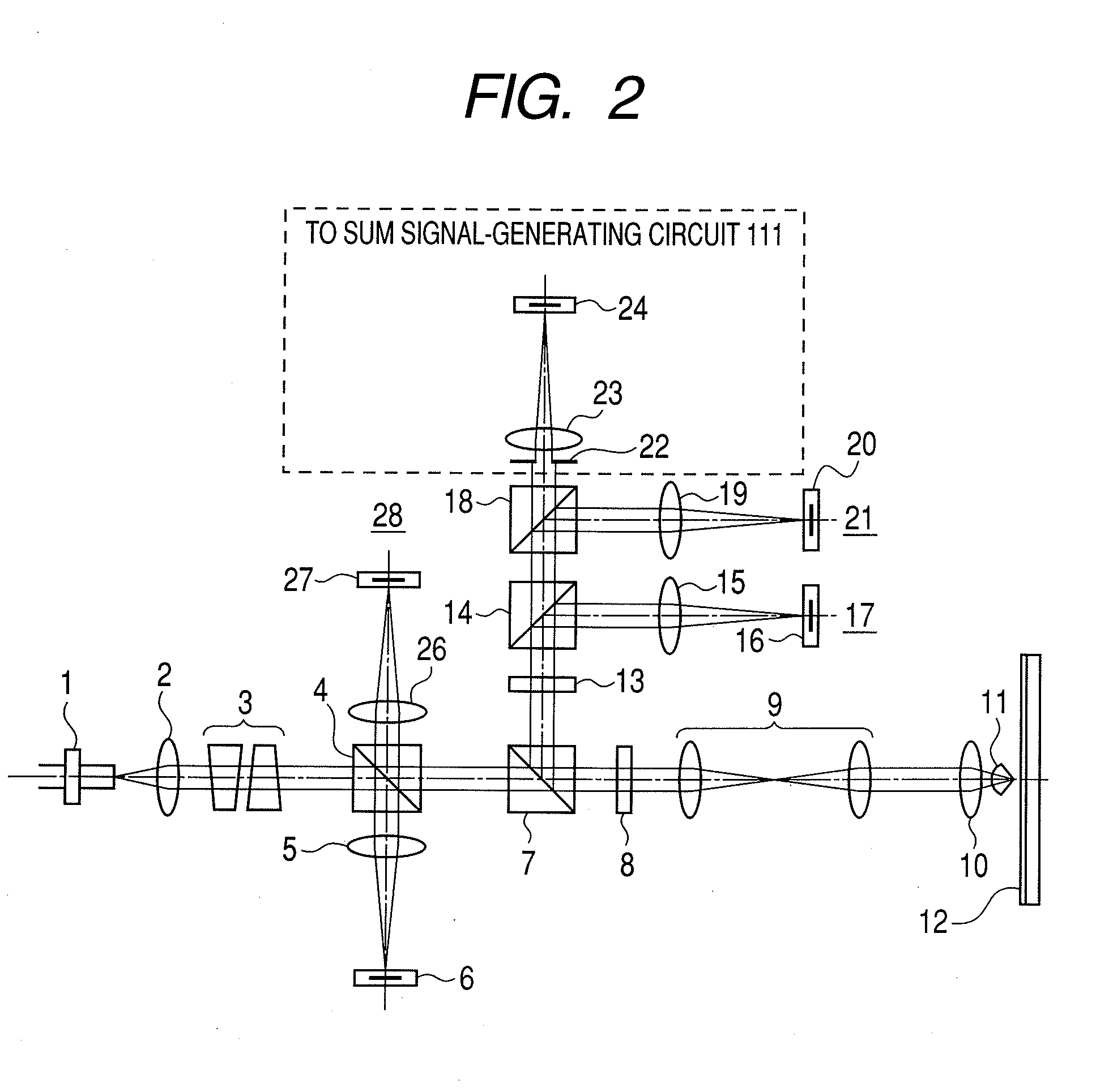
[0052]FIG. 1 is a block diagram of First Embodiment of the optical information recording-reproduction apparatus of the present invention. In FIG. 1, the same symbols are used for denoting corresponding items as in FIG. 13 describing the prior art technique. FIG. 2 illustrates constitution of the optical system (optical pickup) of this Embodiment. FIG. 2 is different, in the portion surrounded by a broken line, from FIG. 13 illustrating a prior art.

[0053]The optical recording medium (optical disk 12) in FIG. 2 corresponds to optical disk 101 in FIG. 1. In FIG. 1, are omitted the circuit for recording information on the optical disk, the circuit for reproduction of information, the circuits for servo-control of focusing and tracking, and the circuit and mechanism for control of optical disk rotation. The same omission is made also in the Embodiment described later (The focus servo circuit is not omitted in the drawings in the Embodiments described later).

[0054]Firstly, the constitutio...

second embodiment

[0067]FIG. 7 is a block diagram for Second Embodiment of the present invention. In FIG. 7, the same symbols are used as in FIG. 1 for denoting corresponding members and items. FIG. 8 illustrates constitution of the optical system (optical pickup) of this Embodiment. In FIG. 8, the same symbols are used as in FIG. 2 for denoting corresponding members. This Second Embodiment is different from First Embodiment in that a focus error signal is generated together with a sum signal from the output from photodetector (PD4) 24 which receives the light beam of NA101 in FIG. 7 corresponds to optical disk 12 in FIG. 8.

[0068]Focus error-generating circuit 113 detects a focus error signal from the output from photodetector (PD4) 24. The focus error signal can be generated, for example, by use of a toric lens as sensor lens 23, and a four-division sensor as photodetector (PD4) 24 according to a conventional astigmatism method.

[0069]The light beam of NA101, enabling generation of the focus error si...


PUM

PropertyMeasurementUnit
wavelengthaaaaaaaaaa
refractive indexaaaaaaaaaa
thicknessaaaaaaaaaa

Abstract

An optical information recording-reproduction apparatus comprises: a light source; an objective lens and a SIL (solid immersion lens) for focusing a light beam from the light source on an optical recording medium; an aperture element for collecting a part of the light beam reflected by an optical recording medium, corresponding to the effective aperture number of the objective lens and SIL of less than 1; a detecting element for detecting the part of the light beam from the aperture element corresponding to the effective aperture number of less than 1; a speed-generating circuit for reducing the speed of approach of the SIL to the recording medium in accordance with the level of the signal detected by the detecting element; and a driver circuit for driving the objective lens and the SIL in accordance with output from the speed-generating circuit.

Description

BACKGROUND OF THE INVENTION[0001]1. Field of the Invention[0002]The present invention relates to an optical information recording-reproducing apparatus which employs a solid immersion lens (hereinafter referred to as a “SIL”) for recording or reproducing information on a recording medium. In particular, the present invention relates to servo-control of a gap or a focus.[0003]2. Description of the Related Art[0004]For increasing the recording density of an optical disk, generally the light spot diameter on the recording face of the optical disk is made smaller by shortening the wavelength of light for recording and reproduction and increasing the numerical aperture (NA) of the objective lens. Conventionally, a so-called SIL is employed and a front lens of an objective lens system is brought close to the recording face to a distance of a fraction (e.g., ½ or less) of the recording light wavelength to increase the NA to be higher than 1 in the air.[0005]A method for this is disclosed i...

Claims


Application Information

Patent Timeline
Patent Type & Authority Applications(United States)
IPC IPC(8): G11B7/00
CPCG11B7/0945G11B7/1203G11B7/1201G11B7/0956G11B7/121G11B7/122
Inventor WATANABE, FUMITO
Owner CANON KK
Why Eureka
Try Eureka