
Stowable cup holder tray assembly

a cup holder and assembly technology, applied in the direction of washing racks, machine supports, other domestic objects, etc., can solve the problem of limiting the passage between the seat assemblies by the occupants of the vehicle, and achieve the effect of improving the cargo carrying capacity of the vehicl

Inactive Publication Date: 2011-02-22
GM GLOBAL TECH OPERATIONS LLC
View PDF14 Cites 15 Cited by
  • Summary
  • Abstract
  • Description
  • Claims
  • Application Information

AI Technical Summary

Benefits of technology

The present invention provides a stowable cup holder tray assembly for vehicles that includes a stowage compartment with a bottom portion and plurality of sidewalls, a cover member hinged to one of the sidewalls, and a cup holder tray member movable between a stowed position and a deployed position. The stowage volume is sufficient to receive the cup holder tray member when in the stowed position. The assembly is positioned adjacent to at least one interior seat assembly of the vehicle and can be mounted below, partially below, or above the interior floor structure. The cover member selectively locks at a right angle with respect to the interior floor structure and the cup holder tray member selectively locks at a right angle with respect to the cover member when in the deployed position. The assembly includes track members and rod members pivotably disposed with respect to each other, which selectively lock within the track members to maintain the cup holder tray member in the deployed position. The technical effects of the invention include improved cargo carrying capacity and unobstructed movement for occupants of the vehicle, as well as a compact and conveniently stowed design.

Problems solved by technology

The center console, although convenient for storage, may limit the passage between the seat assemblies by the occupants of the vehicle.

Method used


Image

  • Stowable cup holder tray assembly
  • Stowable cup holder tray assembly
  • Stowable cup holder tray assembly

Examples


Embodiment Construction

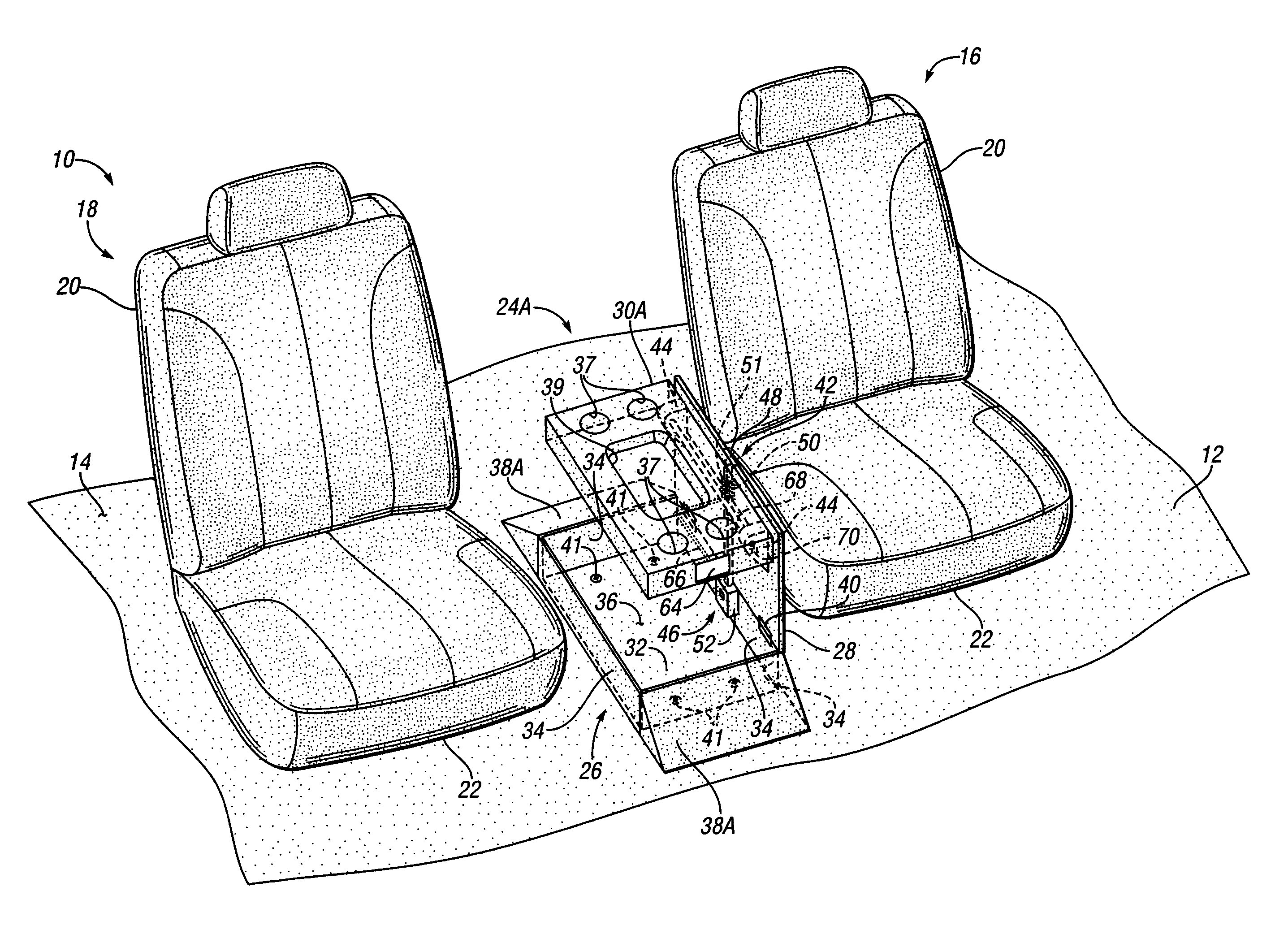
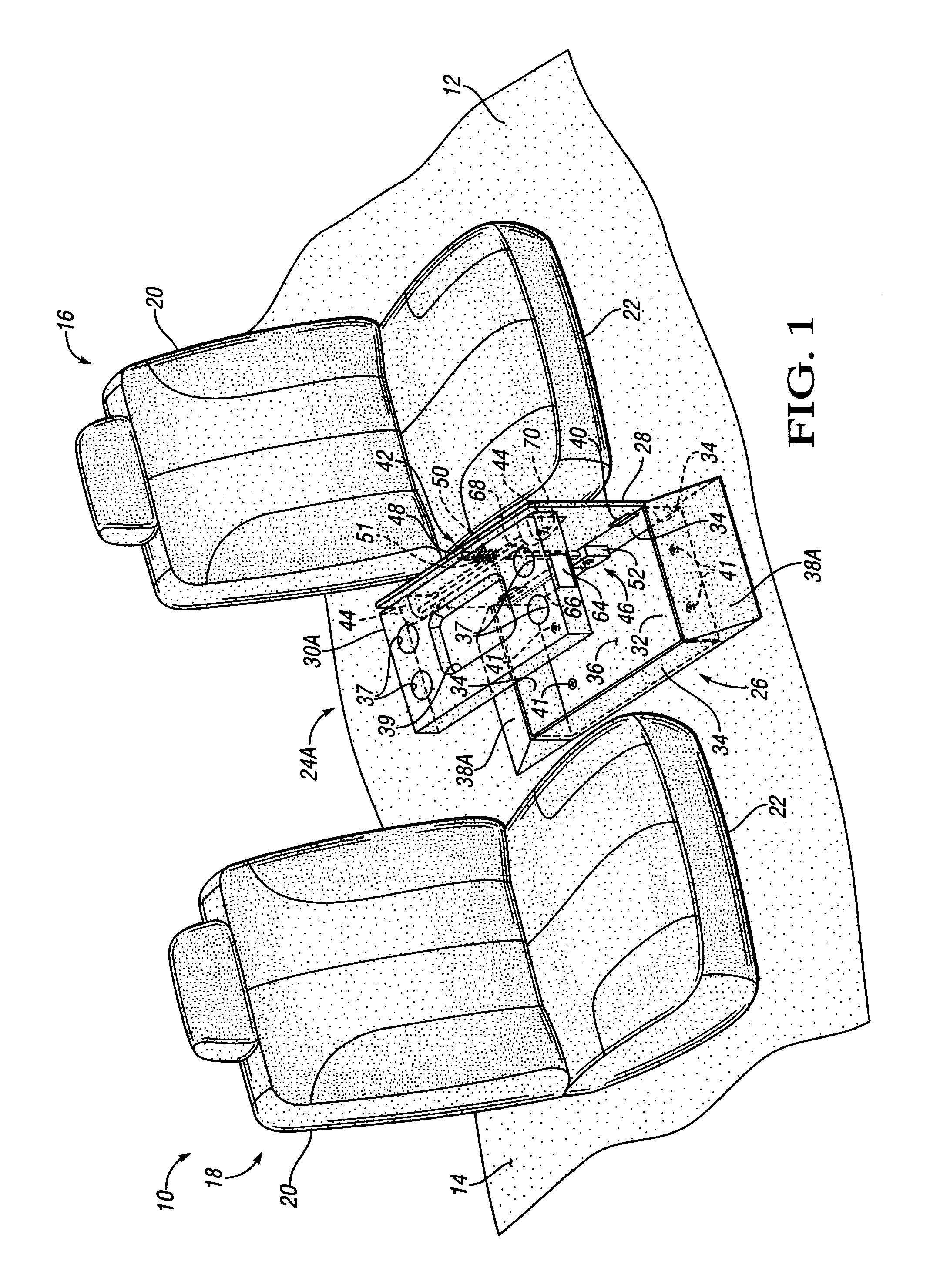
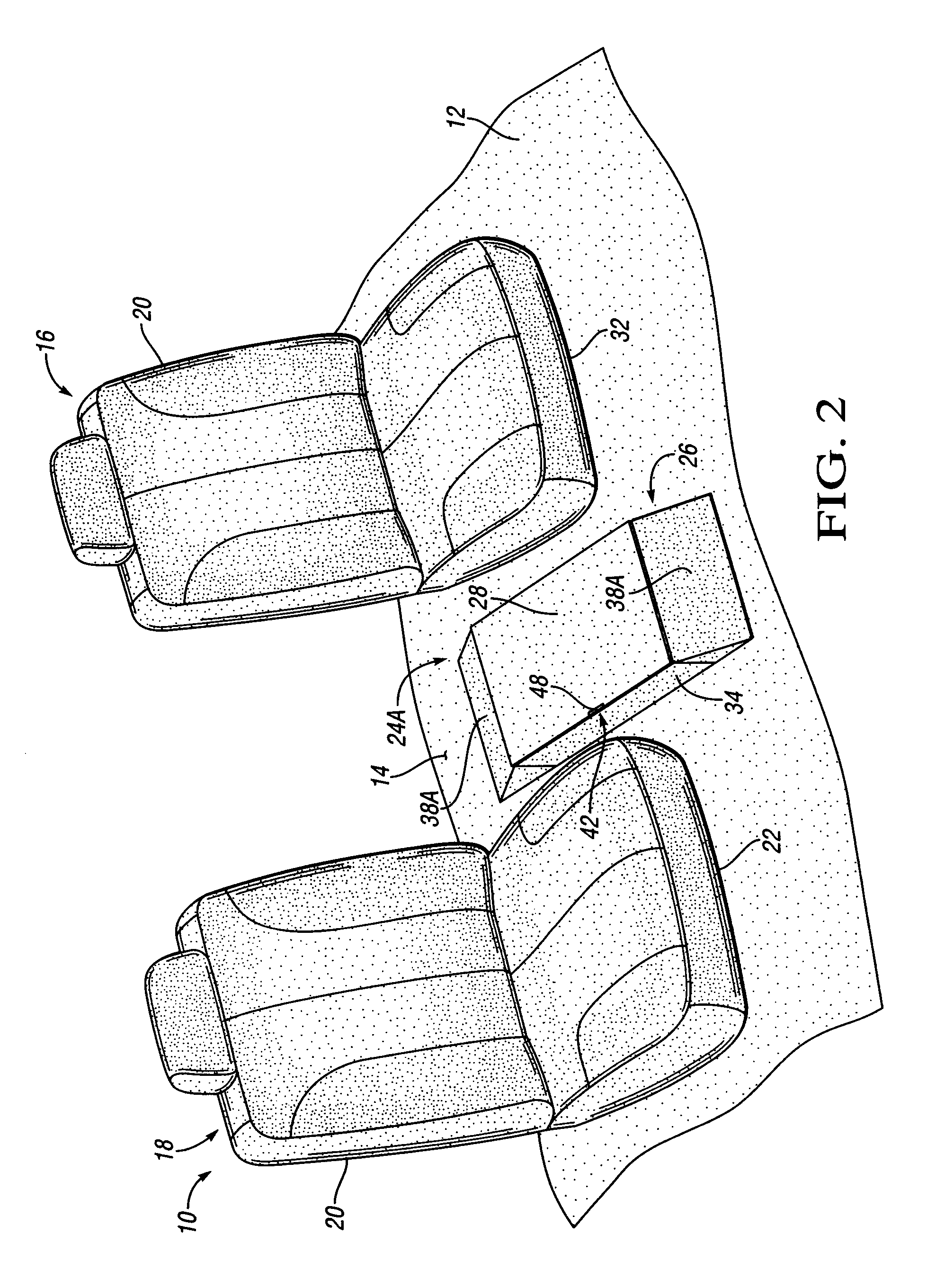
[0017]Referring to the drawings wherein like reference numbers correspond to like or similar components throughout the several figures, there is shown in FIG. 1 a portion of a vehicle 10 such as, for example, a mini-van, sport utility, conversion van, etc. The vehicle 10 includes an interior floor structure 12, which operates to at least partially define an interior volume 14. A first and second seat assembly 16 and 18, respectively, is mounted with respect to the interior floor structure 12. The first seat assembly 16 and second seat assembly 18 are spaced from each other and may constitute a first vehicle seating row or a second vehicle seating row. When configured as a first vehicle seating row, the first seat assembly 16 may function as the driver's seat upon which the operator, not shown, of the vehicle 10 will sit to effect operation thereof. Additionally, the second seat assembly 18 may function as a passenger seat. When configured as a second vehicle seating row, each of the...


PUM


Abstract

A stowable cup holder tray assembly is provided for a vehicle having an interior floor structure. The cup holder assembly includes a stowage compartment having a bottom portion with a plurality of opposing sidewalls extending therefrom and defining a stowage volume. The stowage compartment is mounted substantially adjacent to the interior floor structure. A cover member is hinged to one of said plurality of opposing sidewalls and operates to substantially close said stowage volume. A cup holder tray member is movable between a stowed position and a deployed position. The stowage volume is sufficiently configured to receive said cup holder tray member when in said stowed position. A vehicle incorporating the disclosed cup holder tray assembly is also provided. The cup holder tray assembly is configured to be sufficiently close to the floor when in the stowed position to provide limited barriers within the interior of the vehicle.

Description

TECHNICAL FIELD[0001]The present invention relates to a cup holder tray assembly for a vehicle.BACKGROUND OF THE INVENTION[0002]Traditionally, vehicles have been provided with cup holders sufficiently configured to retain a beverage container for the convenience of the occupants of the vehicle. These cup holders may be mounted to a dash panel, door, or center console of the vehicle. The center console is typically a stationary member positioned between seat assemblies. The center console defines a volume for storage of items and may include one or more cup holders. The center console, although convenient for storage, may limit the passage between the seat assemblies by the occupants of the vehicle.SUMMARY OF THE INVENTION[0003]A stowable cup holder tray assembly is provided for a vehicle having an interior floor structure and at least one seat assembly mounted thereto. The at least one seat assembly includes a lower seat member. The cup holder assembly includes a stowage compartment...

Claims


Application Information

Patent Timeline
Patent Type & Authority Patents(United States)
IPC IPC(8): A47K1/08
CPCB60N3/102B60N3/12Y10S224/926
Inventor HADDAD, MICHEL E.MORRIS, STEVEN E.
Owner GM GLOBAL TECH OPERATIONS LLC
Learn More