Container and manufacturing method thereof

A production method and container technology, applied in the field of containers, can solve the problems of reduced container load capacity, high container production cost, and improved container body, so as to achieve the effects of saving resources, simplifying the production process, and increasing the load capacity

Inactive Publication Date: 2017-01-04
SHENGSHI CONTAINER MANAGEMENT SHANGHAI
View PDF6 Cites 5 Cited by
  • Summary
  • Abstract
  • Description
  • Claims
  • Application Information

AI Technical Summary

Problems solved by technology

[0006] The purpose of the present invention is to provide a container to solve the problem that each component of the existing container is usually designed to be of equal wall thickness, which causes waste of raw materials and makes the production cost of the container higher, and also increases the weight of the container body itself, resulting in a technical issue with reduced cargo capacity
[0007] Another object of the present invention is to provide a manufacturing method of the above-mentioned container, to solve the problem that the various components of the existing container are usually designed to have equal wall thickness, which causes waste of raw materials and makes the production cost of the container higher, and also increases the cost of the container. The weight of the box body itself leads to the technical problem of reducing the cargo capacity of the container

Method used


Image

  • Container and manufacturing method thereof
  • Container and manufacturing method thereof
  • Container and manufacturing method thereof

Examples


Embodiment 1

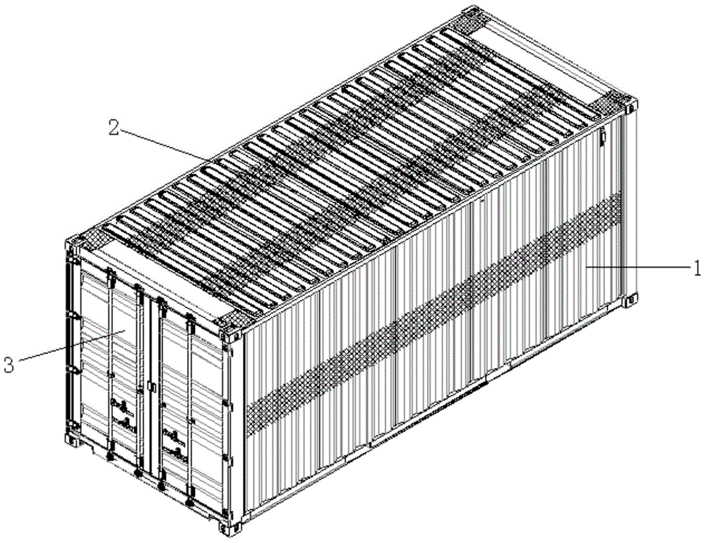
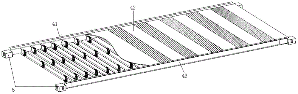
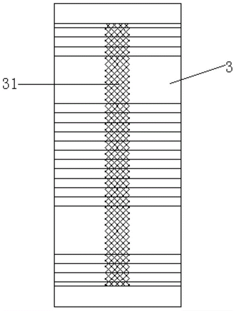
[0048] The container of the present invention comprises a bottom frame, a door end plate and a front end plate respectively set up at both ends of the bottom frame in the length direction, a pair of side plates respectively set up on both sides of the bottom frame in the width direction, and horizontally arranged on the door end plate, the front end plate and the front end plate. The top plate at the top of the side plate, the underframe includes two bottom side beams parallel to each other, two front and rear end beams parallel to each other, a plurality of bottom beams transversely connected to the two bottom side beams, and a bottom beam laid on the bottom beams For the floor, the wall thickness of the door end plate 3 changes regularly in its length or width direction, and its thin-walled area 31 is distributed at intervals with thick-walled areas, such as image 3shown. The thick-walled area can be arranged along the length or width of the centerline of the door end plate...

Embodiment 2

[0050] The container of the present invention comprises a bottom frame, a door end plate and a front end plate respectively set up at both ends of the bottom frame in the length direction, a pair of side plates 1 respectively set up on both sides of the bottom frame in the width direction, and horizontally arranged on the door end plate and the front end plate. and the top plate at the top of the side plate 1, the underframe includes two bottom side beams parallel to each other, two front and rear end beams parallel to each other, a plurality of bottom beams transversely connected to the two bottom side beams and laying on the bottom beams On the floor, the wall thickness of the side plate 1 changes regularly in the direction of its length or width, and its thin-walled area 11 and thick-walled area are distributed at intervals, such as Figure 4 shown. The thick-walled area can be arranged along the long or wide centerline of the side panel 1 , or can be arranged at other part...

Embodiment 3

[0052] The container of the present invention comprises a bottom frame, a door end plate and a front end plate respectively set up at both ends of the bottom frame in the length direction, a pair of side plates respectively set up on both sides of the bottom frame in the width direction, and horizontally arranged on the door end plate, the front end plate and the front end plate. The top plate at the top of the side plate, the underframe includes two bottom side beams parallel to each other, two front and rear end beams parallel to each other, a plurality of bottom beams transversely connected to the two bottom side beams, and a bottom beam laid on the bottom beams For the floor, the wall thickness of the front plate varies regularly in the direction of its length or width, and its thin-walled areas and thick-walled areas are distributed at intervals. The thick-walled area can be arranged along the long or wide centerline direction of the front end plate, and can also be arrang...


PUM


Abstract

The invention discloses a container and a manufacturing method thereof. The container comprises a bottom frame, a door end plate, a front end plate, side plates and a top plate. The bottom frame comprises bottom side beams, a front end beam, a rear end beam, a plurality of bottom cross beams and a floor laid on the bottom cross beams. The thickness of at least one structure part of the door end plate, the front end plate, the side plates, the top plate, the bottom side beams, the front end beam, the rear end beam and the bottom cross beams changes regularly in the length or width direction of the structure part, and a thin-walled zone and a thick-walled zone of the structure part are distributed in a spaced mode. Compared with the prior art, on the premise that the bending strength and rigidity of the container are kept unchanged, the steel consumption is reduced, raw material waste is avoided, resources are saved, cost is reduced, the self weight of the container is further reduced, the cargo capacity of the container is increased, and the container has the advantage of being environmentally friendly.

Description

technical field [0001] The invention relates to the technical field of containers, in particular to a container and a manufacturing method thereof. Background technique [0002] As the main carrier of international freight, containers are widely used in air transportation, Among the various modes of combined transport combining shipping and land transport, it is considered to be an important carrier to realize multiple combined transport of sea + land + air. [0003] From the perspective of container box structure, it usually includes side panels, door end panels, front end panels, top panels and underframes. The underframe generally includes bottom side beams, front and rear end beams, bottom beams and floors laid on the bottom beams. [0004] The main raw material of the container is steel, which is generally designed to be of equal wall thickness. However, through finite element analysis, it is found that the stress distribution of each component of the container is dif...

Claims


Application Information

Patent Timeline
Patent Type & Authority Applications(China)
IPC IPC(8): B65D88/10B65D90/02
Inventor 刘彦斌许双龙
Owner SHENGSHI CONTAINER MANAGEMENT SHANGHAI
Why Eureka
Try Eureka