Motor vehicle

a motor vehicle and chassis technology, applied in the field of motor vehicles, can solve the problems of unfavorable vehicle structure, vehicle structure can be placed under strain, unfavorable vehicle safety and comfort, etc., and achieve the effect of reducing the possibilities

Inactive Publication Date: 2011-02-22
VALMET AUTOMOTIVE
View PDF38 Cites 12 Cited by
  • Summary
  • Abstract
  • Description
  • Claims
  • Application Information

AI Technical Summary

Benefits of technology

[0007]The objective of the invention is to broaden the possibilities for the course of the struts and their connection to the chassis for a motor vehicle.
[0011]The avoidance of a bending stress results, in particular, when the spacing of the strut mountings at the connection support in the vehicle transverse direction is less than 120 millimeters.
[0013]It is also possible that the struts are formed to be vibration selective, and associated with these are a pick-up unit for the take-up of longitudinal stresses occurring during driving, and at least one actuator element for effecting a force to counteract the longitudinal stresses, so that an active stabilization of the vehicle against outside stimuli is possible.

Problems solved by technology

With motor vehicles there is the problem, in general, that outside stimuli of vibrations occurring during driving operation, such as when driving over uneven roadways, for example potholes or upwards projecting swells, can cause undesired vibrations and torsions of the chassis.
Thus, driving safety and comfort can be impacted and the vehicle structure can be placed under strain.
This problem occurs notably in cabriolet vehicles having an integral body-frame, which, due to the non-rigid roof, which especially in the open state cannot reinforce the chassis, have a stability disadvantage in comparison with closed vehicle bodies.
For vehicles with a low lying rear axle or other special geometric characteristics, the difficulty occurs that the struts usually lying horizontally under the bottom would hit on an obstacle, and the prior possibility of strut localization on the underbody is more difficult, or is completely impossible.
However, for torsion the system is over-determined.
In addition, for adverse chassis conditions, such as a low-lying rear axle, such a construction cannot be assembled.

Method used


Image

  • Motor vehicle
  • Motor vehicle
  • Motor vehicle

Examples


Embodiment Construction

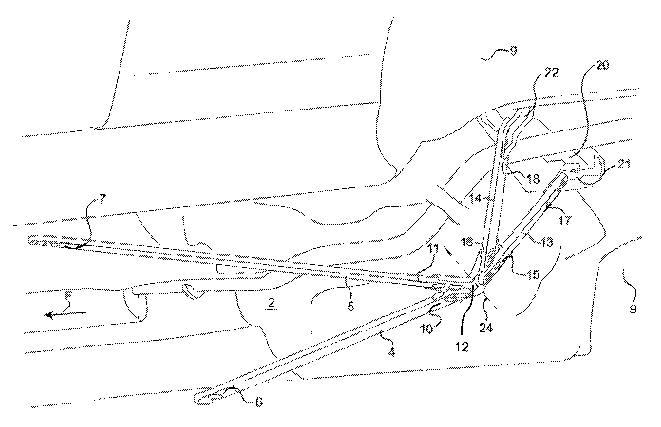
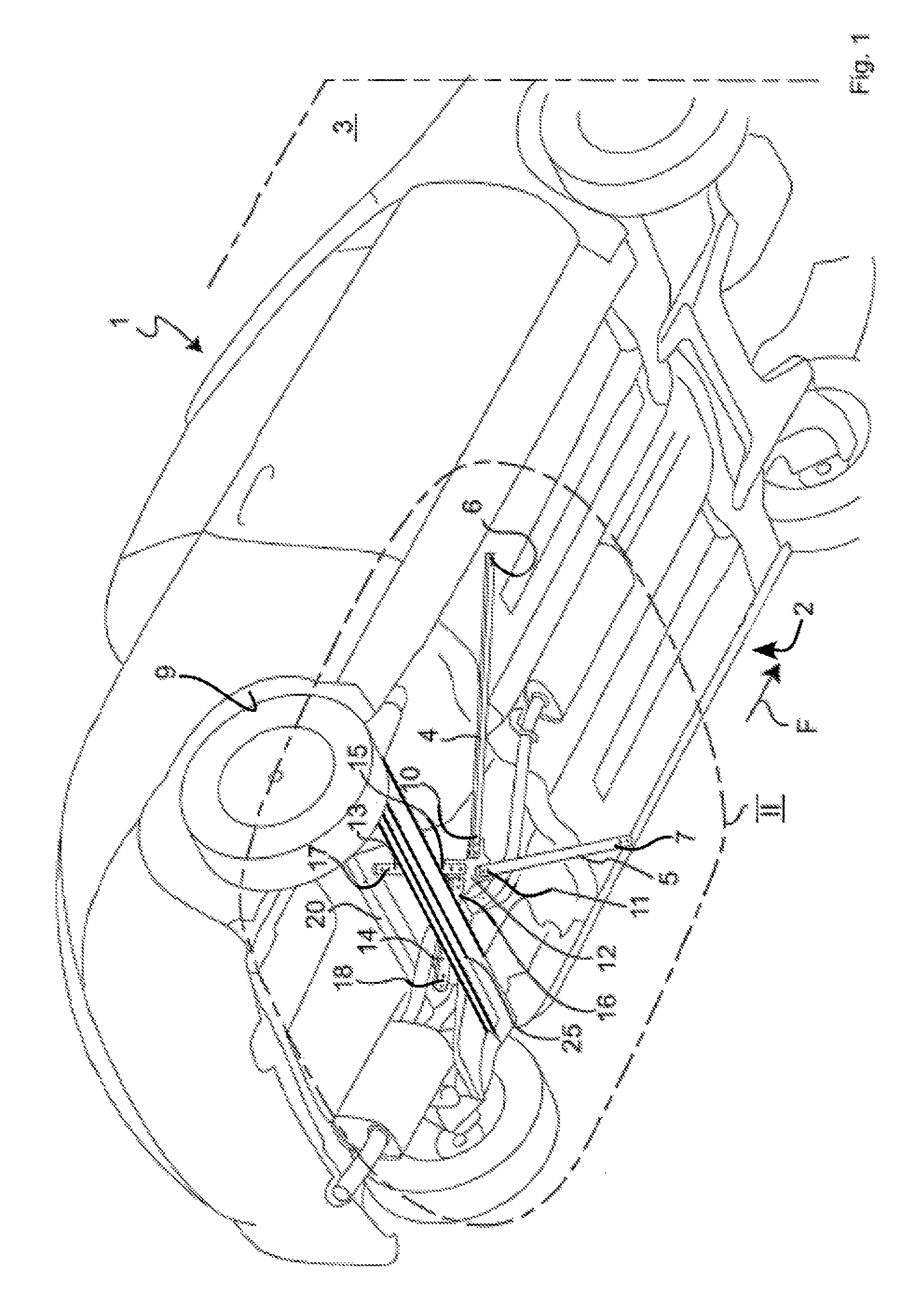
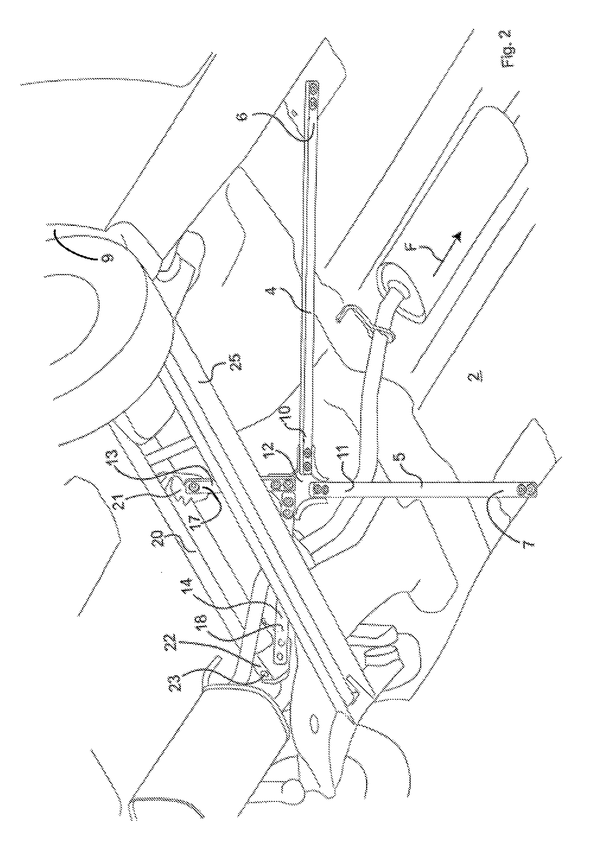
[0024]In the illustrated practical example according to FIG. 1, a first pair of bracing struts 4, 5 that are at least nearly symmetrical about a vertical longitudinal mid-plane 3, is associated, at least in the rear half of the vehicle, with the underbody 2 of a vehicle 1—here a cabriolet vehicle, which is not essential. In addition, further struts can lie in the front area of the vehicle. The number and symmetrical arrangement of the struts 4, 5 shown in the drawing are only to be viewed as an example, as is their trend.

[0025]The struts 4, 5 here are mounted via brackets, in each case, with their forward ends 6, 7 in the direction of travel F, to the underbody 2 of the vehicle 1 in its outer transverse edge area, for example, at side beams. In the present practical example, they are detachably screwed to the underbody 2, to which end above the underbody 2 there are provided, in each case, abutments—not shown—that are separate and supplied with internal threads. Also, a riveting or ...


PUM


Abstract

A motor vehicle, especially a cabriolet vehicle, with a motor vehicle chassis is provided to whose underbody area at least two reinforcing struts are allocated, each of which trends from a chassis attachment with a component in the direction of a vertical longitudinal mid-plane. A connection support is provided free under the underbody and with a distance to it, at which support two of these struts are held in close distance to each other with respect to the vehicle transverse direction, as well as two further struts, which from there extend away, in each case, with a component in the direction of the vertical longitudinal mid-plane, wherein the connection support is angled about at least one axis extending transverse to the vehicle between the mountings for the two struts and the mountings for the two further struts.

Description

CROSS-REFERENCE TO RELATED APPLICATION(S)[0001]This application is a US National Phase of International Application No. PCT / DE 2005 / 000691, filed Apr. 15, 2005, which claims priority to German 10 2004 018 977.3, filed Apr. 20, 2004. The entire contents of the above identified applications are incorporated herein by reference.TECHNICAL FIELD[0002]The invention relates to a motor vehicle, especially a cabriolet vehicle, with struts associated with its underbody area.BACKGROUND OF THE INVENTION[0003]With motor vehicles there is the problem, in general, that outside stimuli of vibrations occurring during driving operation, such as when driving over uneven roadways, for example potholes or upwards projecting swells, can cause undesired vibrations and torsions of the chassis. Thus, driving safety and comfort can be impacted and the vehicle structure can be placed under strain. This problem occurs notably in cabriolet vehicles having an integral body-frame, which, due to the non-rigid roof...

Claims


Application Information

Patent Timeline
Patent Type & Authority Patents(United States)
IPC IPC(8): B62D21/06B62D25/08B62D25/20
CPCB62D21/06B62D25/20B62D25/087
Inventor WESTING, FRANZBENTE, ANDREASPARTMANN, VINZENZ
Owner VALMET AUTOMOTIVE
Why Eureka
Try Eureka