Printer

a printing machine and printing technology, applied in the field of printing machines, can solve the problems of broken optical disks and damage to the cutter mechanism itself, and achieve the effect of preventing the rigid recording medium from being damaged and preventing the cutter from being malfunctioning

Inactive Publication Date: 2011-02-22
CASIO COMPUTER CO LTD
View PDF32 Cites 4 Cited by
  • Summary
  • Abstract
  • Description
  • Claims
  • Application Information

AI Technical Summary

Benefits of technology

[0010]It is therefore an object of the present invention to provide a printer that when a rigid recording medium such as an optical disk is set in the printer body, prohibits the operation of the cutter means by the user, thereby preventing the rigid recording medium from being damaged and preventing the cutter means from being malfunctioning. It is another object of the prevent invention to provide a printer which prevents the operator from operating the cutter means to cut / damage the rigid recording medium or from causing the cutter means itself to be damaged, and prevents the user from inadvertently opening the cover closed against the printer body to exchange print expendables in a state in which the rigid recording medium is inserted into the inlet in the cover, thereby damaging the rigid recording medium.
[0012]According to this arrangement, the prohibiting means prohibits the user from operating the cutting means when the rigid recording medium is received in the conveyance path. Thus, the operator cannot operate the cutting means, and damage to the rigid recording medium by the cutting means and damage to the cutting means due to its operation on the rigid recording medium are prevented.
[0026]According to this arrangement, when the rigid recording medium is received within the conveyance path, the prohibiting means prohibits the operation of the cutting means by the user and the opening of the cover. Thus, the recording medium is protected from being damaged and / or the cutting means from being damaged due to the user's operation of the cutting means. In addition, the recording medium is protected from being damaged due to the user's inadvertent opening of the cover in a state where the rigid medium is received in the inlet in the cover.

Problems solved by technology

However, if the cutter mechanism operates wrongly in printing on the optical disk, the optical disk would be broken.
Furthermore, if the cutter mechanism, which is designed so as to cut a thin printing tape, acts on the optical disk, the cutter mechanism itself would be damaged.
However, when the cover is inadvertently opened with the optical disk set in the printer body, the edge of the inlet in the cover may hit on the label face of the optical disk, thereby damaging the same.

Method used


Image

  • Printer
  • Printer
  • Printer

Examples


first embodiment

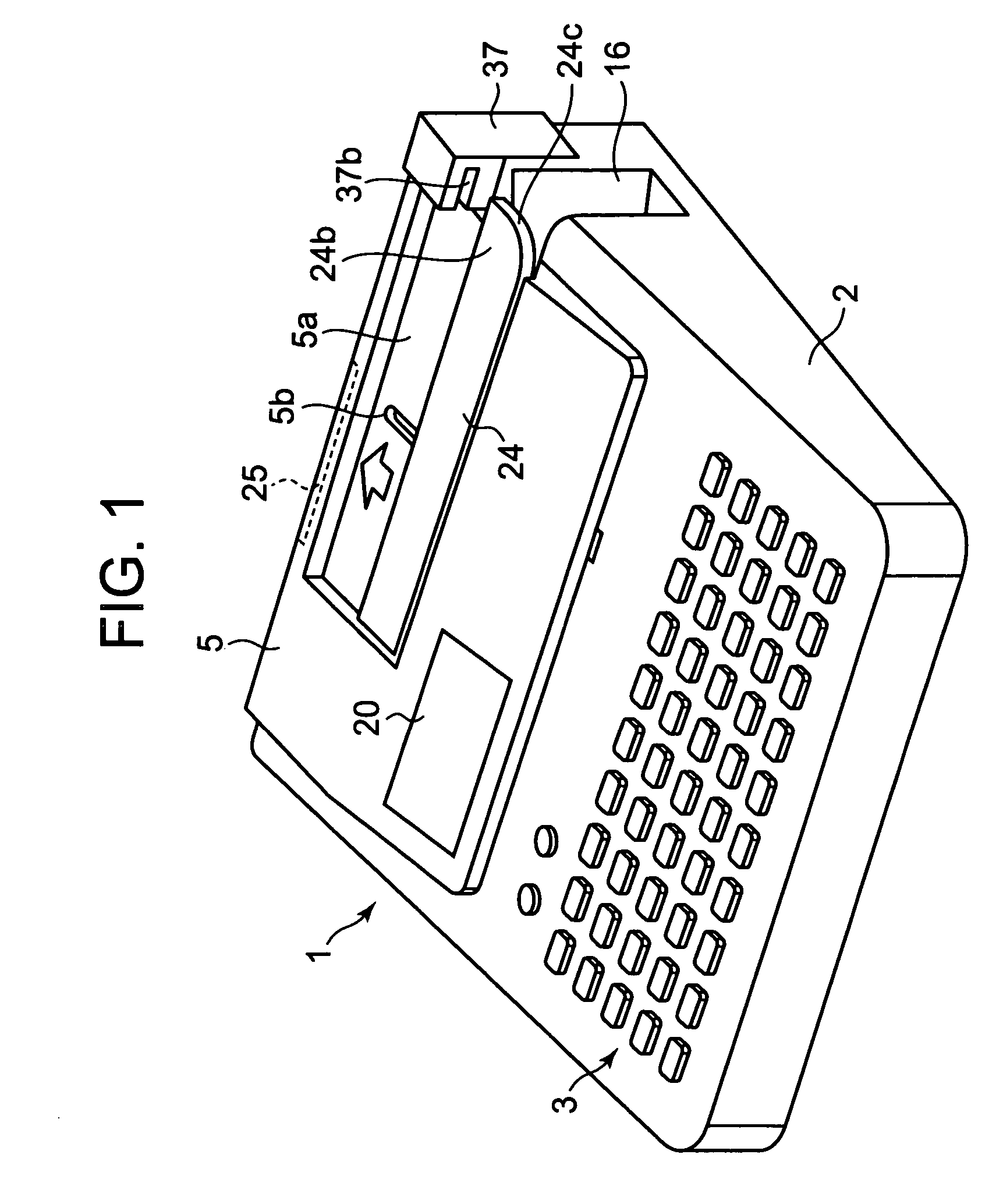
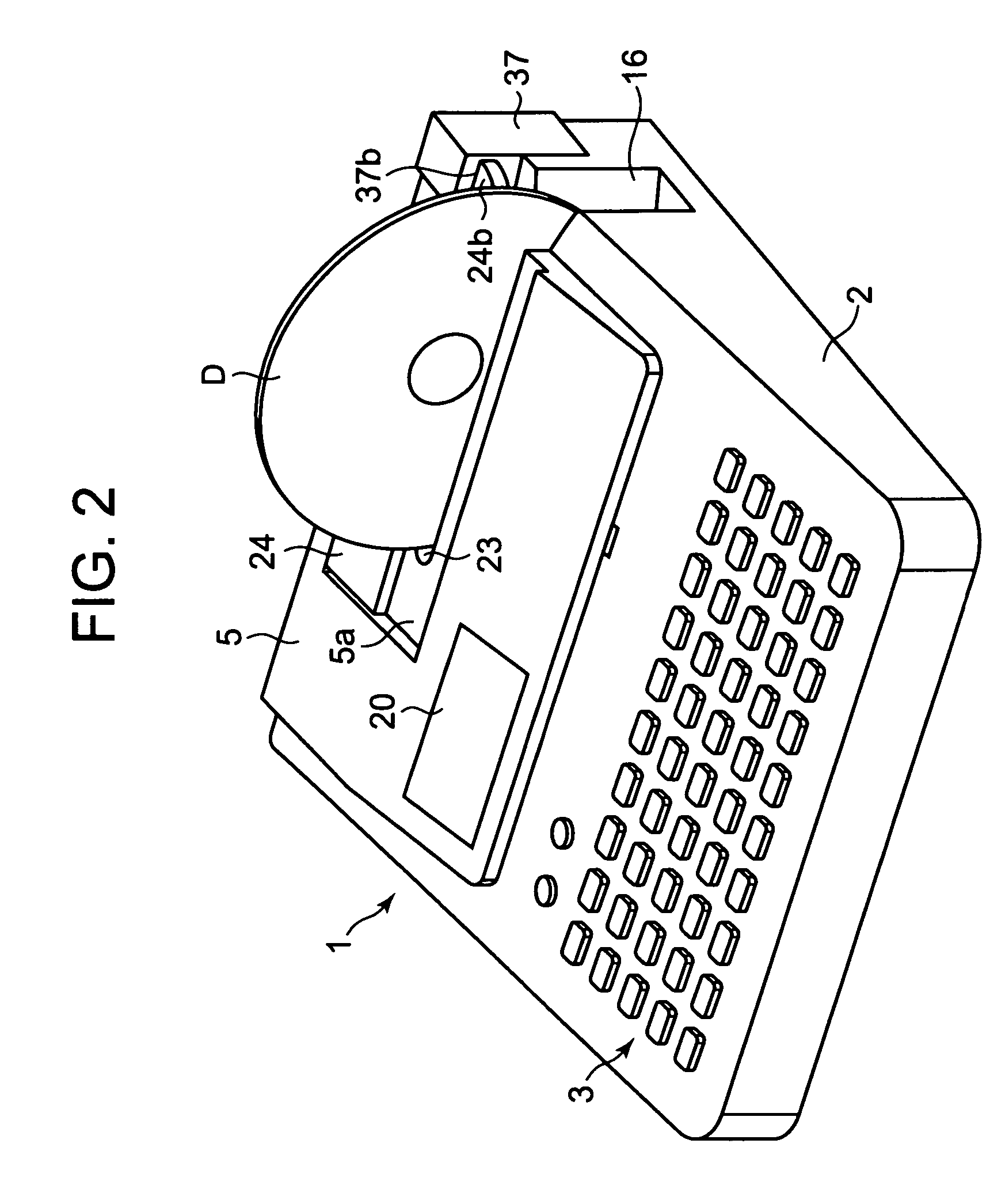
[0072]Embodiments and modifications of the present invention will be described with reference to the accompanying drawings. FIG. 1 is a perspective view of a printer according to the present invention. FIG. 2 is a perspective view of the FIG. 1 printer with an optical disk set in the printer. FIG. 3 is a perspective view of the printer with a cover open. FIG. 4 is a plan view indicative of an internal structure of the printer.

[0073]The printer should print directly on a label (or printing) face of a disk-like rigid recording medium (or optical disk) such as a data recordable CD-R (Compact Disk-recordable) or a DVD-R (Digital Versatile Disk-Recordable) and also print on a soft tape-like printing medium (or printing tape).

[0074]The printer comprises a printer body 1 having a body case 2 and a cover 5. A key-in unit 3 and a display 4 provided on an upper surface of the body case 2. The key-in unit 3 comprises character keys for inputting character string data to be printed, a print key...

second embodiment

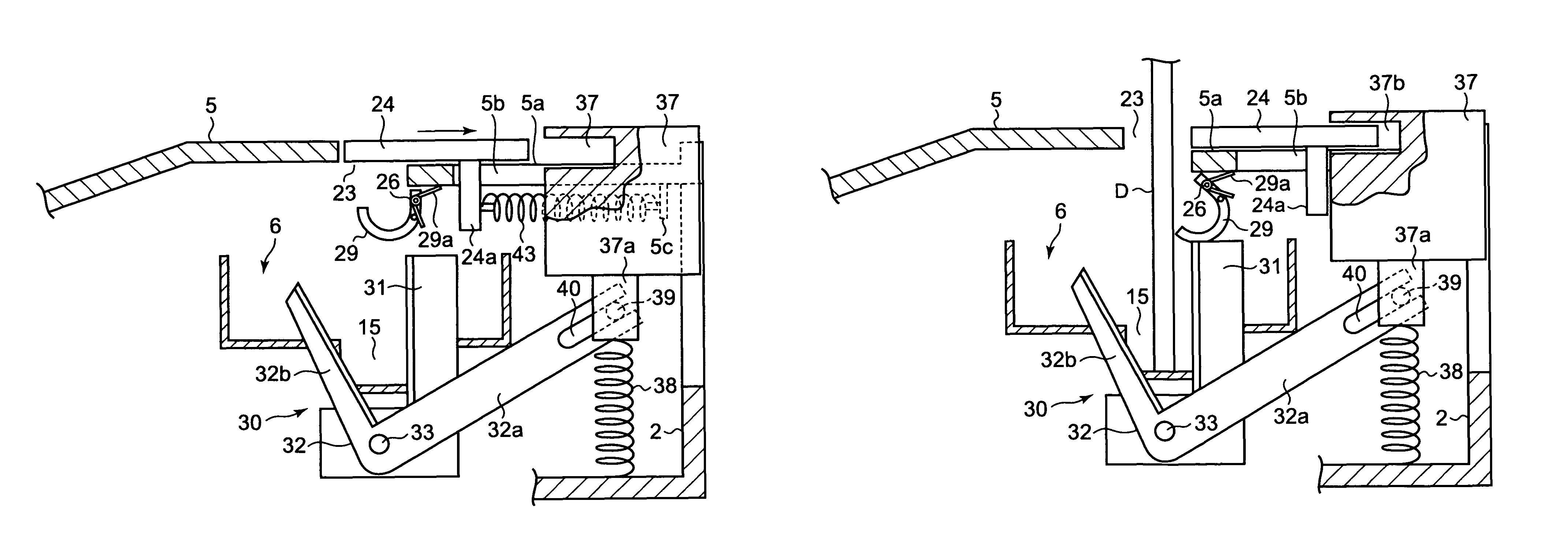
[0106]In this second embodiment, as shown in FIG. 11, when the optical disk D is inserted upstanding into the printer body 1 from its open end 16, the optical disk D hits the inclined edge 24c of the inlet cover 24, which moves the inlet cover 24 against the resiliency of the spring 43 backward on the printer body 1 to a position where the inlet cover 24 overlaps at its right-hand end with the upper end of the cutter button 37, thereby covering the cutter button 37, as shown in FIGS. 11 and 12B. Thus, the user cannot manually press the cutter button 37 down and hence operate the cutter 30.

[0107]When the optical disk D is printed and then taken out of the printer body 1, and more particularly, the open end 23, the inlet cover 24 is moved forward on the printer body 1 by the resiliency of the spring 43, which causes the engaging end 24b of the inlet cover 24 to move away from above the cutter button 37, thereby exposing the top of the cutter button 37 and causing the inlet cover 24 to...

third embodiment

[0114]As described above, according to the printer of the third embodiment, when in disk printing the inlet cover 24 is moved manually backward on the printer body 1 to open the inlet 23, the cutter button 37 is locked by the engaging end 24b of the inlet cover 24, thereby disabling the cutter 30. Thus, when the optical disk D is printed in the printer body 1, the movable blade 32 does not operate, thereby damaging no optical disk even when the cutter button 37 is advertently pushed down manually.

[0115]FIGS. 16-18 show a fourth embodiment in which as in the second embodiment the cutter button 37 is movable vertically relative to the body case 2. The cutter button 37 is elastically pushed upward by a compression spring 38 such that the cutter button 37 is flush with the body case 2. As in the third embodiment the inlet cover 24 is received manually slidable back and forth within a recess 5a of the cover 5 on the printer body 1. A manual knob 24d is provided at the midpoint of the len...


PUM


Abstract

A printer in which when an optical disk is inserted into a conveyance path in a printer body, an inlet cover is moved to a position where the inlet cover opens an inlet in a cover provided on the printer body. This causes a cutter button that operates a cutter for a tape-like printing medium to be locked by the inlet cover. Thus, when the optical disk is printed, the cutter is rendered inoperable. Accordingly, the printer can prevent a trouble such as inadvertently operates the cutter, thereby damaging the disk or the cutter itself.

Description

BACKGROUND OF THE INVENTION[0001]1. Field of the Invention[0002]The present invention relates to printers and more particularly such printer that prints on a selected one of a rigid medium such as an optical disk and a printing tape inserted into the printer body.[0003]2. Description of the Related Art[0004]In the past, printers that print characters, composing a title for data recorded on an optical disk (or recording medium) such as a CD-R (Compact Disk-Recordable), on the same are known, for example, as disclosed in Published Unexamined Japanese Patent Application No. 2003-72175. This printer comprises a tray that supports an optical disk and a printer mechanism that prints on the optical disk. The tray is movable between outside of the printer body and an predetermined position within the printer body. The printer mechanism comprises a carriage reciprocal over the tray when the same is disposed at the predetermined position within the printer body. The carriage supports a recipr...

Claims


Application Information

Patent Timeline
Patent Type & Authority Patents(United States)
IPC IPC(8): B41J11/70B41J3/407B41J29/00
CPCB26D7/24B41J3/4071B41J11/703B41J11/009B41J3/4075B41J11/0095
Inventor KIMURA, SATOSHIMOCHIZUKI, YOSHIAKI
Owner CASIO COMPUTER CO LTD
Why Eureka
Try Eureka