Concrete finishing apparatus

a technology of concrete finishing and leveling equipment, which is applied in the direction of in situ paving, construction, and roads, can solve the problems of high quality and super-flat concrete floors that are typically much more difficult and expensive to consistently achieve than those conventionally produced, and can not be particularly easy or inexpensive to achieve, and achieves a high degree of flatness and smoothness. , the effect of high degree of quality and low relative effort or cos

Active Publication Date: 2011-02-22
SOMERO ENTERPRISES INC
View PDF154 Cites 18 Cited by
  • Summary
  • Abstract
  • Description
  • Claims
  • Application Information

AI Technical Summary

Benefits of technology

[0009]The present invention is intended to provide a concrete floor or surface finishing apparatus which is operable to finish a surface of a partially set-up concrete slab or floor to a higher degree-flatness and smoothness than is currently available using known or conventional methods. The apparatus of the present invention requires minimal manual labor processes to achieve the desired floor surface quality. Additionally, the apparatus of the present invention is applicable to large floors and surface areas, whereby the entire floor surface can achieve the desired high level of quality with little extra relative effort or cost.
[0011]In one form, the at least one rotatable ring working member may comprise a single ring that is installed on a machine (such as, for example, a typical concrete power trowelling machine that is well known within the concrete construction industry). The single rotatable ring working member may be attached to the outer portions of the rotating trowelling blades at the internal diameter of the ring. Thus, the addition of the single rotatable ring working member may encompass the rotating blades of the power trowelling machine and increases the effective overall diameter of the machine, as well as the surface contact surface area of engagement with the concrete.
[0012]In another form, the concrete finishing apparatus may include at least two rotatable ring working members mounted at the outer periphery of the movable unit. Rather than only using a single rotatable ring working member rotating in a single direction and in unison with a set of rotating blades, such a two ring configuration provides a first rotatable ring working member driven in either direction relative to the rotation of the blades, and a second rotatable ring working member (of a larger diameter than the first and concentrically and additionally added to the outside perimeter of the first rotatable ring member) driven in a direction opposite the direction of rotation of the first ring. With such a configuration, the average resultant torque reaction at the handlebars of a walk behind concrete power trowelling machine may be substantially reduced or limited. The second ring also provides the advantages of further increasing the working surface contact area of the machine, and therefore further improves both the productivity machine and the resulting quality of the concrete surface.
[0013]According to another aspect of the present invention, a concrete finishing apparatus for smoothing and leveling partially set-up concrete at a support surface includes a movable unit and two sets of rotating blades at the base of the unit for engagement of a partially set-up concrete surface, and at least one (or optionally two or more) rotatable ring working members loosely mounted at the outer periphery of the movable unit. A power trowelling machine with two sets of rotating blades at the base of the unit allows the operator to be positioned on the “ride-on” machine itself while in operation as opposed to the walk behind version.
[0014]The ring member may be driven by a separate drive device or actuator or motor (such as a hydraulic motor or the like), and thus may be driven independently from the driving of the blades of the movable unit. Optionally, and as discussed above, the machine may include two rings, with one ring driven in one direction and the other ring driven in the opposite direction. Optionally, the rotatable inner and outer ring members may be driven at various speeds that are independent of the rotational speed of the two blade assemblies. Such a design feature provides the further advantages of independent drives and operator-selective variable speed control of the separate blade assemblies and the rotating ring concrete finishing members.
[0015]Therefore, the present invention provides a concrete smoothing and leveling apparatus which is capable of finishing a concrete floor or surface to a higher degree of quality while being used and incorporated with the current methods and practices of concrete construction. This emerging state-of-the-art apparatus requires reduced or minimal manual labor processes, few or no additional or new concrete finishing steps, and is inexpensive to operate as compared to existing concrete finishing process machinery and devices.

Problems solved by technology

At an increased level of floor flatness (FF) and floor levelness (FL), specifications between FF 50 and FF 80 and a floor levelness (FL) specification of between FL 50 and FL 80 are typical of close-tolerance upper-level-of-quality floors that are often desired in many building or structural applications but may not be especially easy or inexpensive to achieve.
High quality and super-flat concrete floors are typically much more difficult and expensive to consistently achieve than those conventionally produced.
A relatively large number of skilled workers are required to accurately finish a large floor for example, and production speed of the floor can be relatively slow with conventional processes, tools, and equipment.
Additionally, as skilled workers and operators continue to work with the manual tools and finishing machine devices, such as hand and powered concrete trowels, pan machines and scrapers, for a long period of time, the laborers will tend to tire and fatigue as the job progresses, which can have an adverse affect on the final F-numbers and level of quality of the concrete floor or surface.
However, such spinning tube applications are typically implemented as an initial strike-off tool, such as a screed for striking-off or screeding freshly placed and uncured concrete to the desired grade.
Because these screeding devices are applicable only to freshly poured, uncured concrete, and the use of accurately set forms or guide rails implementation of such devices does not easily result in a close-tolerance or super-flat concrete floor surface.

Method used


Image

  • Concrete finishing apparatus
  • Concrete finishing apparatus
  • Concrete finishing apparatus

Examples


Embodiment Construction

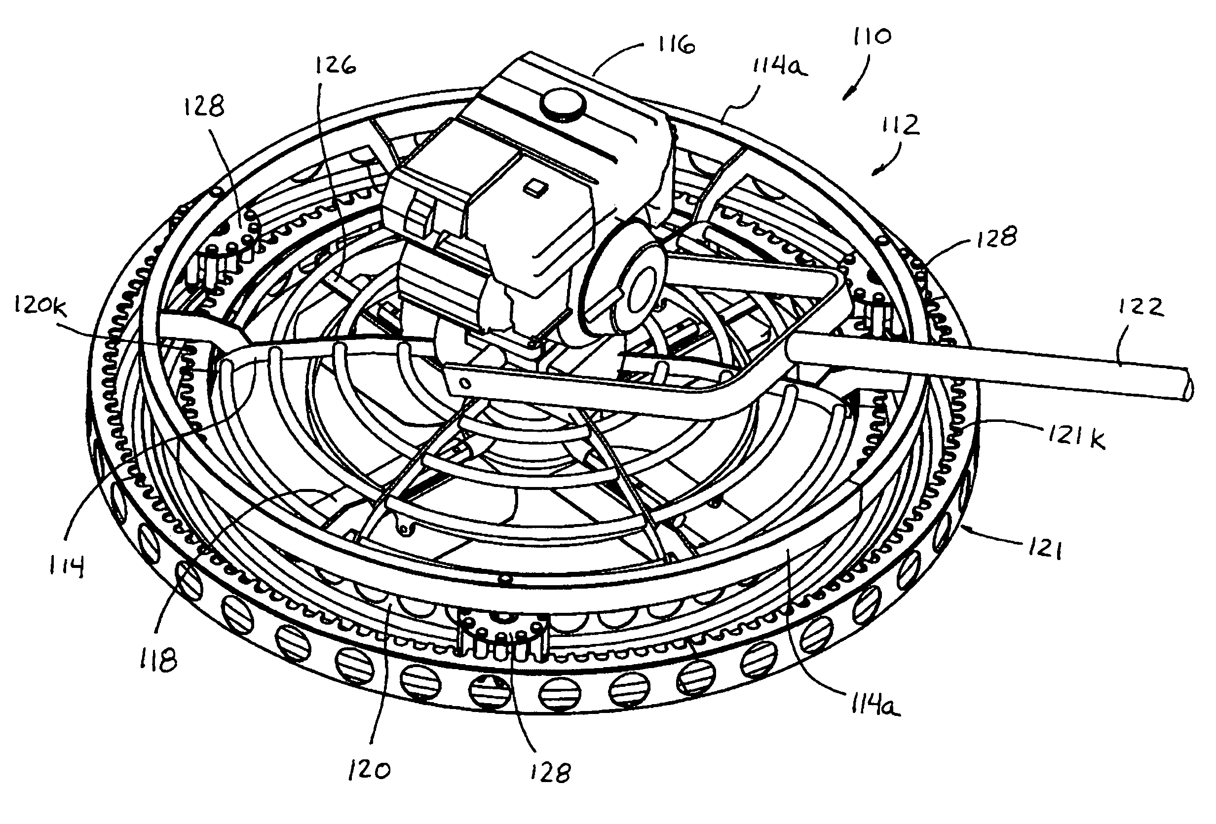
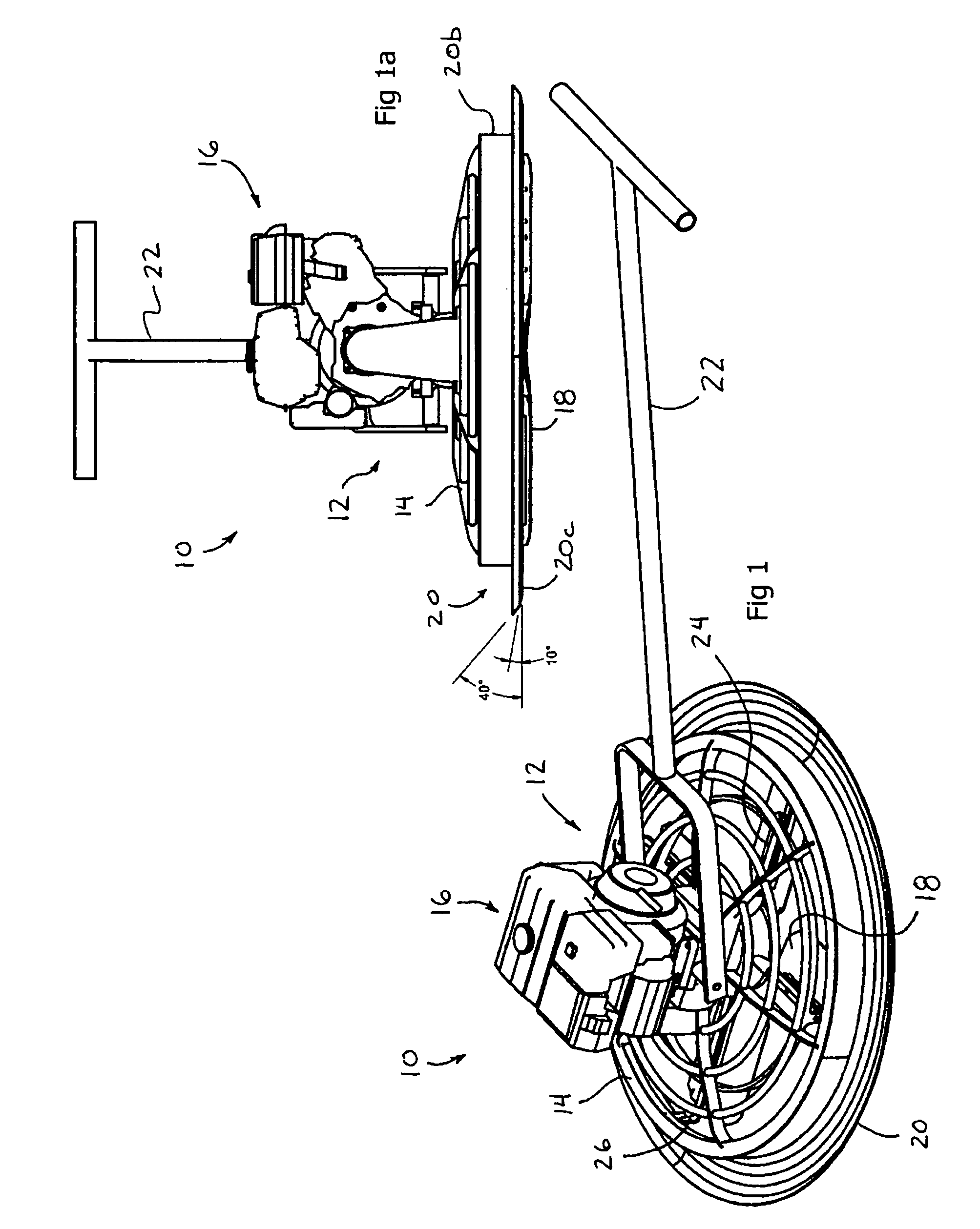
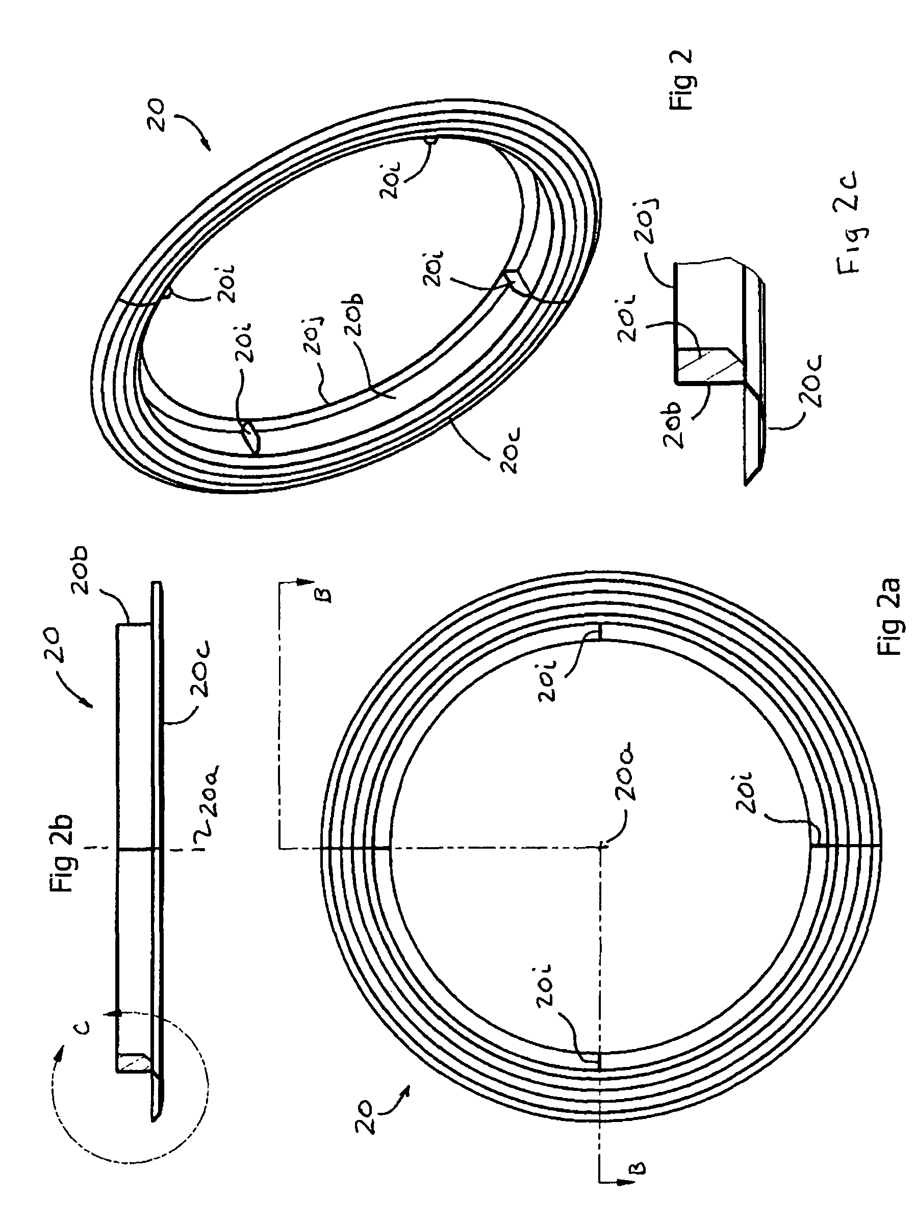
[0043]Referring now specifically to the drawings and the illustrative embodiments depicted therein, a concrete finishing apparatus 10 for smoothing and leveling partially set-up concrete at a support surface includes a movable unit 12 having a frame portion 14, a driving device or drive motor or power source or drive means 16 supported on the frame portion, with a set of rotating blades 18 disposed at the base of the unit for engagement of a partially set-up concrete surface and rotatably driven by the driving device 16, and at least one rotatable ring working member 20 disposed at or mounted at the outer periphery of the movable unit (FIG. 1). The movable unit 12 is movable and supported over and / or on the partially set-up concrete and may be movable in a plurality of desired directions, such as via an operator moving the unit by pushing or pulling at a handle 22. The blades 18 may be rotatably driven about their central axis via the driving device 16, while the rotatable ring work...


PUM


Abstract

A concrete finishing apparatus and method for smoothing and flattening partially set-up concrete to a close-tolerance surface includes a movable unit that is movable and supported at a partially set-up concrete surface and at least one rotatable ring finishing member mounted to the movable unit. The rotatable ring finishing member is positioned at the concrete surface and rotatable to engage and finish the surface of the partially set-up concrete to a higher quality, closer-tolerance flat and level concrete floor surface. The apparatus may include a pair of rotatable ring finishing members that may be rotatable in opposite directions to enhance the floating and finishing processes and to transport any cement paste, sand, small aggregate, or concrete mix residue forward with the rotatable ring finishing members working surfaces to cut high areas and fill in any low areas as the concrete finishing apparatus moves over the partially set-up concrete.

Description

CROSS REFERENCE TO RELATED APPLICATION[0001]The present application claims benefit of U.S. provisional application Ser. No. 61 / 031,796, filed Feb. 27, 2008, which is hereby incorporated herein by reference in its entirety.FIELD OF THE INVENTION[0002]The present invention relates generally to an improvement in a concrete finishing, smoothing and / or leveling apparatus and, more particularly, to a new type of concrete smoothing and leveling apparatus which is operable on partially set-up concrete to increase the smoothness and levelness quality specification of the partially set-up concrete and therefore the final and cured concrete surface.BACKGROUND OF THE INVENTION[0003]There is a growing and consistent need in the concrete construction industry for increased quality close-tolerance, flat and level concrete floors and slabs whereby the finished working surfaces of the floors and slabs being constructed are as flat and level as is economically possible using typical construction meth...

Claims


Application Information

Patent Timeline
Patent Type & Authority Patents(United States)
IPC IPC(8): E01C19/22
CPCE04F21/248E04F21/247
Inventor QUENZI, PHILIP J.SOMERO, DAVID W.MATSON, TRACY L.
Owner SOMERO ENTERPRISES INC
Why Eureka
Try Eureka