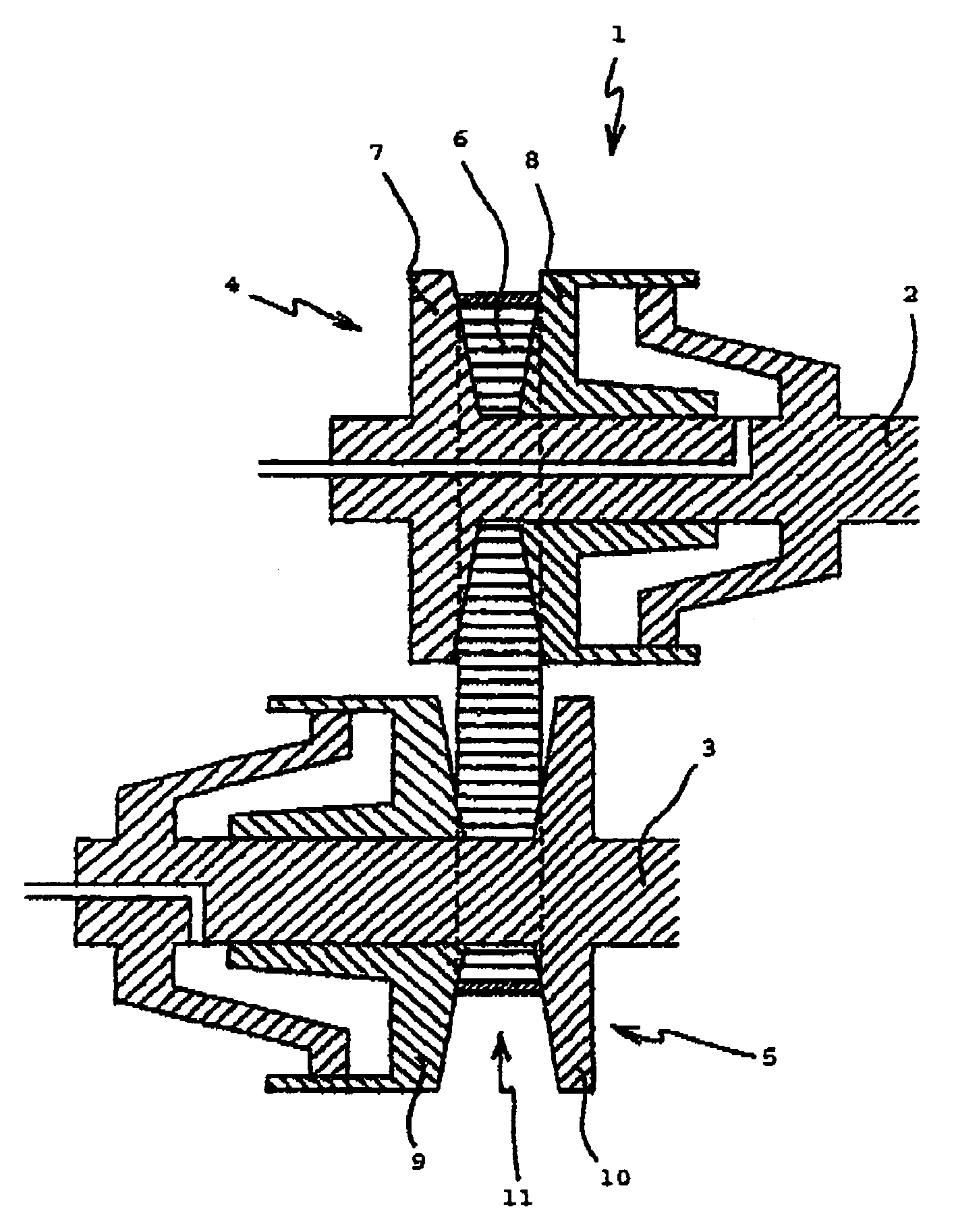
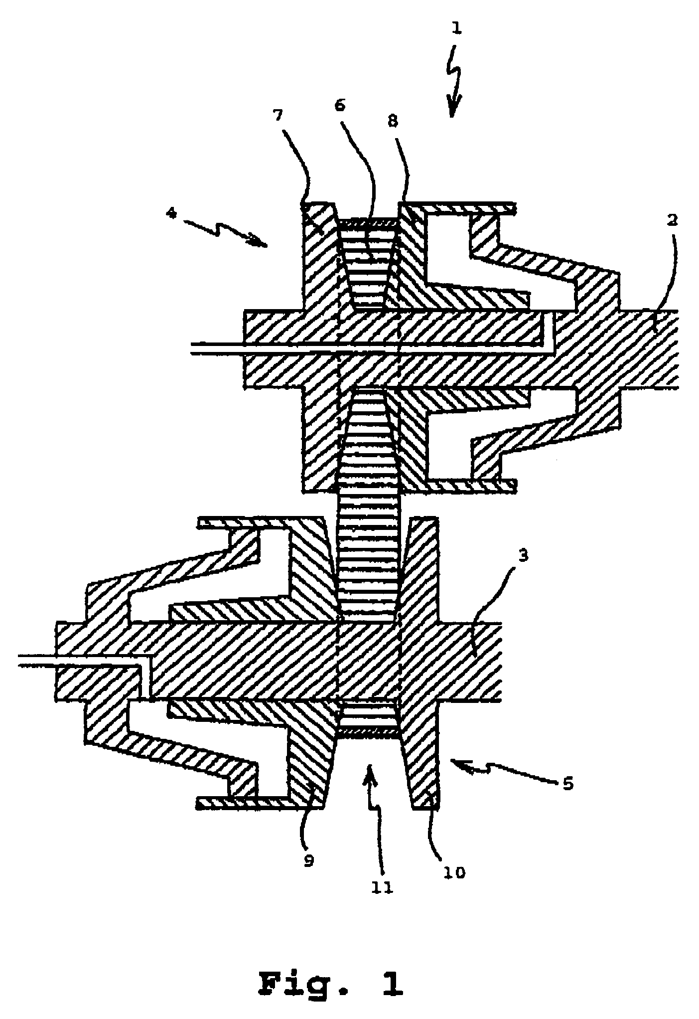
[0029]FIG. 1 shows diagrammatically a continuously variable transmission, such as for utilization in a motor vehicle. The continuously variable transmission is indicated in general by the reference sign 1.
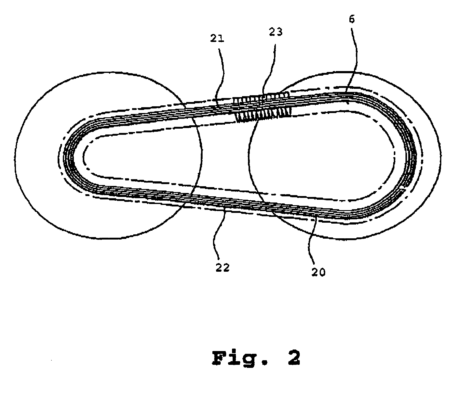
[0030]The continuously variable transmission 1 comprises two pulleys 4 and 5 being arranged on separate pulley shafts 2 and 3. An endless drive belt 6 being shaped like a closed loop is arranged around the pulleys 4 and 5 and serves for transmitting torque between the pulley shafts 2 and 3. The pulleys 4 and 5 are each provided with two conical sheaves 7 and 8 respectively 9 and 10, which collectively form a partially conical receiving groove 11 in which the drive belt 6 is received.
[0031]The transmission ratio of the continuously variable transmission is determined by the ratio of the running radii of the drive belt 6 in the receiving groove 11 of the pulleys 4 and 5. The running radii can be varied by mutually displacing the pulley sheaves 7 and 8 respectively 9 and 10 with the assistance of displacing means, which are not depicted for the sake of the simplicity. For this purpose, at least one of the pulley sheaves 7 and 8 respectively 9 and 10 is arranged in an axially movable manner. For the purpose of transmitting torque between the pulley shafts 2 and 3, the drive belt 6 is clamped inside the receiving groove 11 of the pulleys 4 and 5 with a certain clamping force.
[0032]In FIGS. 2 and 3a, the drive belt 6 is depicted in more detail. The drive belt 6 comprises two endless carriers 20 being disposed next to each other, which in this example are each composed of a number of bands 21 forming a bundle of bands 22. Along the entire length of the carriers 20, transverse elements 23 are arranged, wherein the transverse elements 23 are mutually adjacent to each other and are movable in axial direction relative to the carriers 20. For the sake of the simplicity, in FIG. 2 only a few of these transverse elements 23 are shown.
[0033]In FIG. 3a, the carriers 20 and the transverse element 23 are depicted in transverse view. The transverse element 23 is on both sides provided with recesses 30 in which the bundles of bands 22 are partially received. Moreover, the transverse element 23 comprises on both sides supporting surfaces 31 on which the bundles of bands 22 are supported.
[0034]Furthermore, the transverse element 23 comprises on both sides pulley sheave contact surfaces 32. When the transverse element 23 is inside the receiving groove, contact between the transverse element 23 and a contact surface of the pulley sheave is established through said pulley sheave contact surface 32. A pulley sheave contact surface 32 and a supporting surface 31 which are situated at one side of the transverse element 23 transform into each other through a transition region 33.
[0035]Two subsequent transverse elements 23 are tiltable relative to each other about a contact line 34 which extends between the two transverse elements 23. As is shown in FIG. 3b, the contact line 34 is situated at the position where a slanting part 36 of a back surface 35 of the transverse element 23 is connected to a straight part 37 of said back surface 35. When transverse elements 23 move through, for example, the receiving groove in one of the pulleys during a movement of the drive belt, the mutual contact between two subsequent transverse elements 23 is guaranteed along the contact line 34.
[0036]In FIG. 4a, a detail of the transverse element according to a first preferred embodiment of the invention is depicted.
[0037]With this, the transition region 33 is shown, and also adjacent parts of on the one hand the supporting surface 31 and on the other hand the pulley sheave contact surface 32.
[0038]According to the invention, the transition region 33 comprises two parts having two different curvature radii. With that, a first curvature radius of a first part 40 being situated at the side of the supporting surface 31 is larger than a second curvature radius of a second part 41 being situated at the sight of the pulley sheave contact surface 32.
[0039]A suitable value of the first curvature radius is within a range of 0.5 mm to 3.0 mm, wherein, according to the invention, the value of the first curvature radius is higher than the value of the second curvature radius. Preferably, the first curvature radius has a value of 1.0 mm.
[0040]Suitably, the second curvature radius is smaller than 1.0 mm, and is in addition smaller than the first curvature radius, according to the invention. Preferably, the second curvature radius has a value of 0.3 mm.
[0041]In FIG. 4a, two possibilities of the known shape of the transition region having one curvature radius are depicted through dotted lines. A dotted line being indicated by the reference numeral 42 shows a possibility having a relatively large curvature radius, while a dotted line being indicated by the reference numeral 43 shows a possibility having a relatively small curvature radius. With this, insight is provided on the fact that a large curvature radius relative to a small curvature radius has the advantage that the transition region 33 has a smaller curvature and consequently is less sensitive to damages. This also implies that a large curvature radius relative to a small curvature radius has the disadvantage that the pulley sheave contact surface 32 is smaller. In the shown example of a large curvature radius, the contact line 34 intersects the transition region 33. This has a disadvantageous effect on the stability of the transverse element during a movement of the drive belt. When the transverse element is then inside the receiving groove between a pair of pulley sheaves, the transverse element will sooner be inclined to perform an undesired and disadvantageous tilting movement as a result of the relatively large radial distance between the contact line 34, where during a movement of the drive belt a pushing force is applied between the transverse elements, and an effective point of application on the pulley sheave contact surface 32 of the frictional force which appears between the transverse element and a pulley sheave.
[0042]When, in FIG. 4a, the transition region according to the invention is compared to on the one hand a transition region having one relatively large curvature radius and on the other hand a transition region having one relatively small curvature radius, then the advantages of the shape according to the invention appear clearly. By means of the application of two curvature radii, a shape of the transverse element wherein the contact line 34 intersects the pulley sheave contact surface 32 is possible, and wherein the contact line 34 is also situated at relatively small distance from the supporting surface 31, and with that from the carriers of the drive belt.
[0043]This contributes in a positive way to the stability of the transverse element during a movement of the drive belt.
[0044]Moreover, the first part 40 of the transition region 33 has a relatively small curvature, as a result of which the chance of damage is much smaller than in case of a larger curvature.
[0045]In FIG. 4b, a detail of the transverse element according to a second preferred embodiment of the invention is depicted.
[0046]Just like in FIG. 4a, with this the transition region 33 is shown, and also adjacent parts of on the one hand the supporting surface 31 and on the other hand the pulley sheave contact surface 32.
[0047]In this second preferred embodiment, the pulley sheave contact surface 32 has an otherwise known surface being corrugated by means of bulges 50. In this embodiment, the pulley sheave contact surface 32 is designed to contact a contact surface of a pulley sheave through the bulges 50.
[0048]Preferably, the pulley sheave contact surface 32 is connected to the transition region 33 through a bulge, as is shown in FIG. 4b. Consequently, the second part 41 of the transition region 33 transforms directly into the bulge. An advantage of this shape is that the pulley sheave contact surface 32 extends beyond the contact line 34 as far as possible.
[0049]It will be clear to a person skilled in the art that the scope of the present invention is not limited to the examples discussed above, but that several amendments and modifications thereof are possible without deviating from the scope of the invention as defined in the appended claims.