Universal joint total disc replacement

a total disc and universal joint technology, applied in the field of prosthetic intravertebral discs, can solve the problems of excessive height, deterioration of these natural discs, and removal of diseased or damaged discs

Inactive Publication Date: 2011-02-22
ZIMMER SPINE INC
View PDF12 Cites 39 Cited by
  • Summary
  • Abstract
  • Description
  • Claims
  • Application Information

AI Technical Summary

Problems solved by technology

Disease, trauma and the like, can cause deterioration of these natural discs, eventually requiring removal of the diseased or damaged disc.
Such devices may suffer from a variety of different problems such as excessive height, lack of resistance to bending, fixed axes of rotation, wear debris, and revision complications and risks.

Method used


Image

  • Universal joint total disc replacement
  • Universal joint total disc replacement
  • Universal joint total disc replacement

Examples


Embodiment Construction

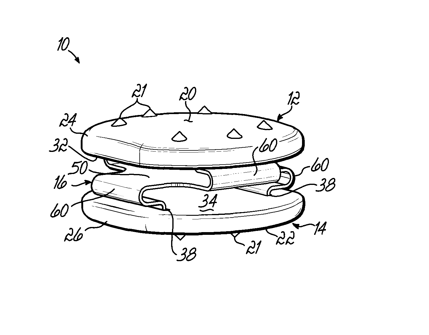
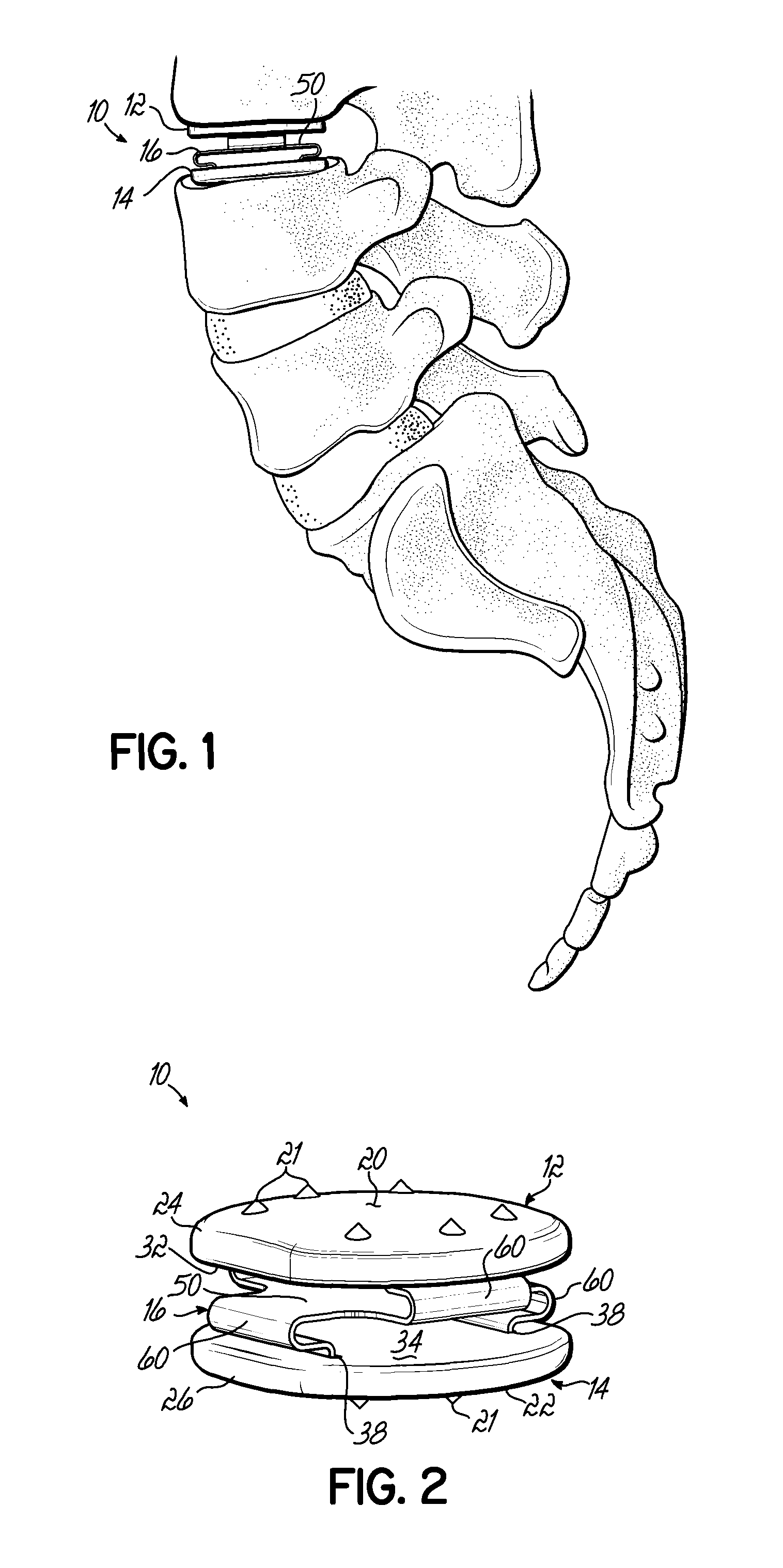
[0025]As shown in FIGS. 1 and 2, a disc replacement 10 is shown in accordance with one embodiment of the present invention and includes a superior end plate 12, an inferior end plate 14, and a U-joint leaf spring 16 positioned between the superior and inferior end plates 12, 14. Both the superior end plate 12 and inferior end plate 14 may include convex exterior surfaces 20 and 22, each surface including a plurality of conical projections 21. Likewise, the end plates 12 and 14 may include chamfered edges 24 and 26, which assist in compression of the disc for insertion as discussed hereinafter.

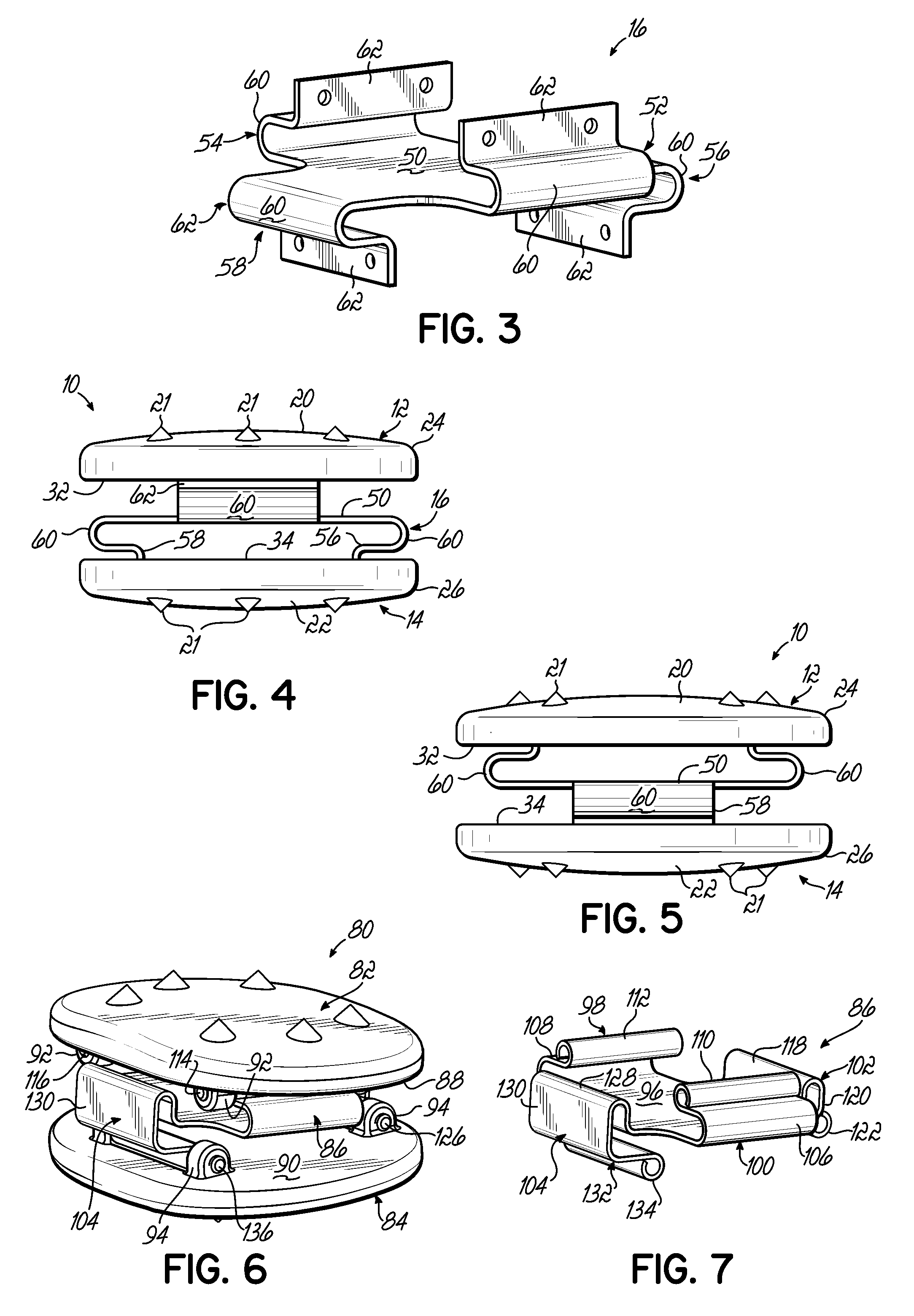
[0026]As shown in FIGS. 1-3, the U-joint leaf spring 16 includes a floating intermediate portion 50. In one embodiment, the intermediate portion 50 may be generally planar. Opposed superior legs 52 and 54 extend from the intermediate portion 50 into slots (not shown) formed in the interior surface 32 of the superior end plate 12. Spring 16 further includes opposed inferior legs 56 and 58, which...


PUM


Abstract

A vertebral disc replacement includes superior and inferior end plates separated by a leaf spring. The leaf spring includes two opposed legs that extend from a floating intermediate portion of the leaf spring to the superior end plate and two opposed legs that extend from the floating intermediate portion to the inferior end plate. The disc replacement device is compact and provides freedom of movement along three axes, translational along the caudal / cranial axis, lateral bending and flexion / extension.

Description

FIELD OF THE INVENTION[0001]The present invention relates to a prosthetic intravertebral disc used to replace a diseased natural disc.BACKGROUND OF THE INVENTION[0002]Vertebral discs separate adjacent vertebral bodies and allow for relative movement between the adjacent vertebral bodies. Disease, trauma and the like, can cause deterioration of these natural discs, eventually requiring removal of the diseased or damaged disc. In certain circumstances, the disc is removed and the adjoining vertebral bodies fused. Alternately, the natural disc can be replaced with a prosthetic disc.[0003]There are a wide variety of prosthetic discs. Many of these use a ball joint type mechanism, such as disclosed in Buttner-Janz et al., U.S. Pat. No. 5,401,269 and Diaz et al., U.S. Pat. No. 7,083,651. Other replacement discs are disclosed in Navarro et al., U.S. Pat. No. 5,534,030 and Patil, U.S. Pat. No. 4,309,777, and Bartish, Jr., et al., U.S. Published application No. 2006 / 0004453. Such devices may...

Claims


Application Information

Patent Timeline
Patent Type & Authority Patents(United States)
IPC IPC(8): A61F2/44
CPCA61F2/442A61F2/4611A61F2/30742A61F2/4455A61F2002/30383A61F2002/30471A61F2002/30571A61F2002/30607A61F2002/4628A61F2220/0025A61F2220/0091A61F2250/0062
Inventor VIKER, THOMAS O.
Owner ZIMMER SPINE INC
Why Eureka
Try Eureka