
Protective mask having removable lens and detachable head strap

a protective mask and lens technology, applied in the field of protective masks, can solve the problems of eye covering lens of a conventional protective mask being directly hit by an exploding paintball, player's vision may be impaired, and the vision available to players through the lens of a conventional protective mask is generally limited to a straight line, so as to prevent paint splatter and solid debris, the effect of maximizing vision

Inactive Publication Date: 2011-03-01
SLY
View PDF12 Cites 10 Cited by
  • Summary
  • Abstract
  • Description
  • Claims
  • Application Information

AI Technical Summary

Benefits of technology

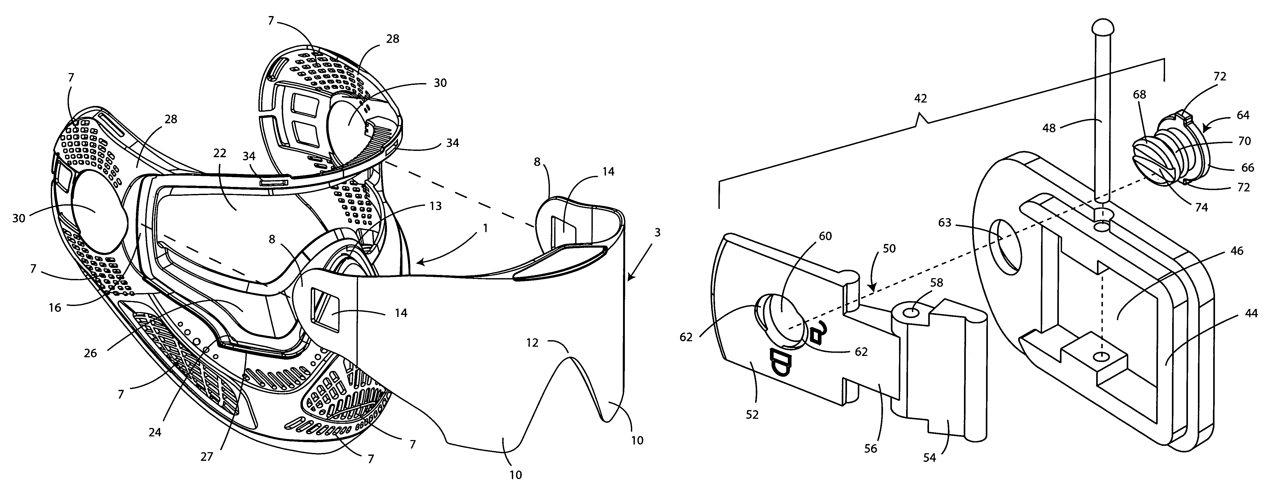
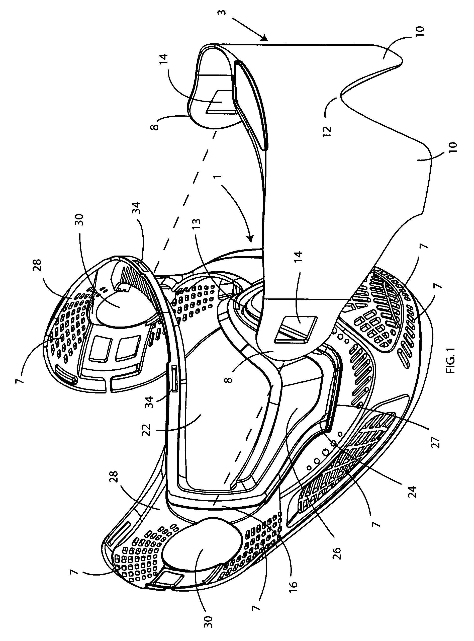
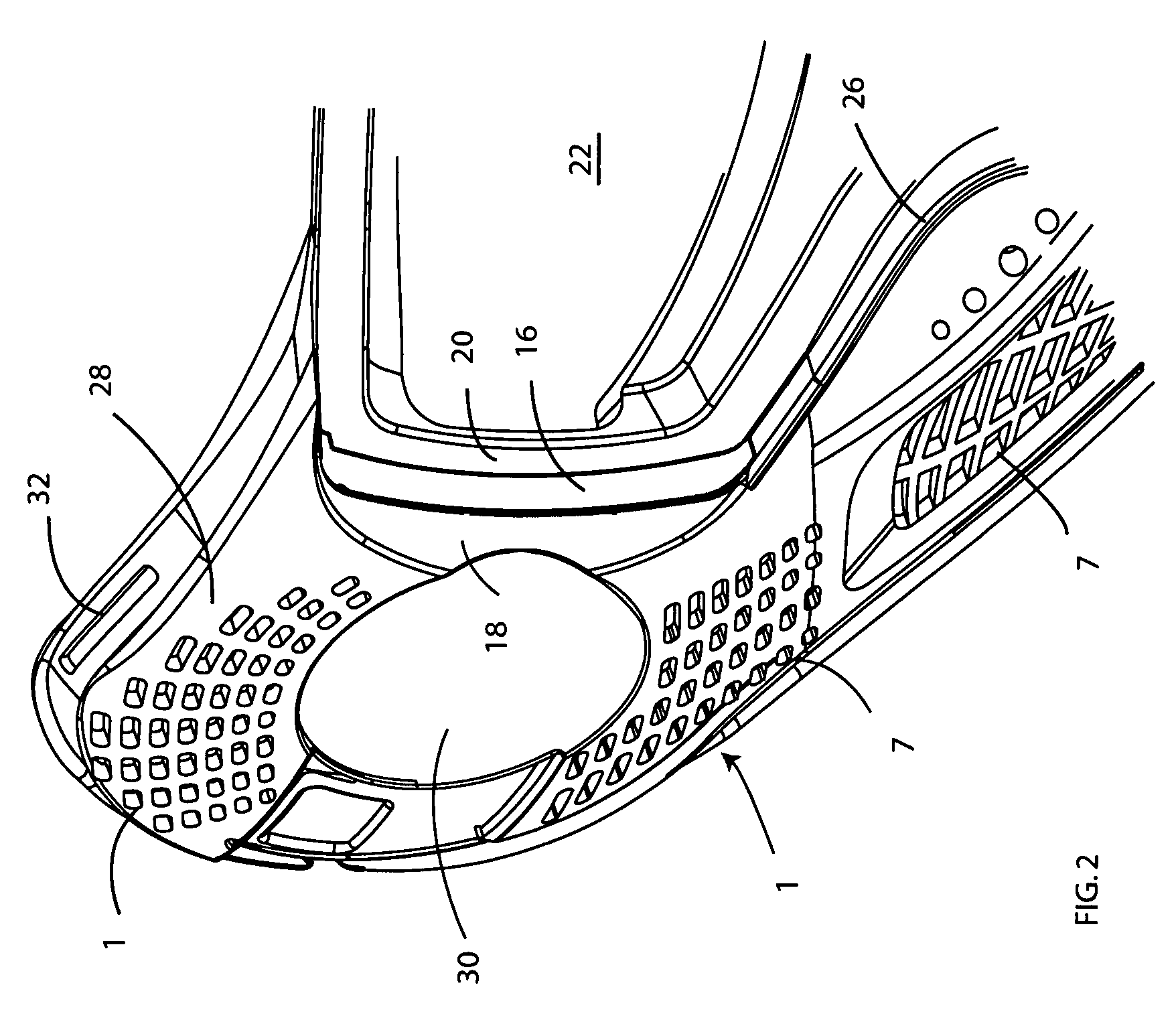
[0011]The lens is removably attached to the protective mask when the ear covering sections of the lens are slidably received through gaps between outer and inner lens guides at each side of the mask. In the assembled configuration, a head strap connection hole formed in each ear covering section of the lens is axially aligned with an ear hole formed in an ear covering section at each side of the mask. The mask has an open front in which the removable lens is located with the eye covering sections thereof seated in respective deep lens receiving pockets that extend to the cheeks of the wearer. The mask is sculpted with downwardly sloping walls running along the lens receiving pockets. Thus, the wearer's vision will be maximized to include a substantially vertical field of view without the wearer having to bend his head. A rib is molded into the mask around the bottom of each lens receiving pocket to establish a ridge or barrier to prevent paint splatter and solid debris from a ruptured paintball from traveling under the lens and obscuring the vision of the wearer.
[0012]Each end of the detachable head strap is tied to a first connector from a pair of connectors that are mated to one another to detachably connect the head strap and the removable lens to the mask. The first connector includes a locking catch that projects inwardly of the mask by way of the axially-aligned ear hole through an ear covering section at one side of the mask and a head strap connection hole through the ear covering section at one side of the lens. The second of the pair of connectors is manipulated against the first connector and includes a rotatable latch having a force-receiving pad at one end and a force-responsive tail at the opposite end. A manual pushing force applied by the wearer to the force-receiving pad of the latch of the second connector causes the force-responsive tail to rotate around a pin and into interlocking mating engagement with the locking catch of the first connector, whereby the first and second connectors are coupled together to prevent a detachment of the head strap and a separation of the removable lens from the protective mask.

Problems solved by technology

In particular, the vision available to a player through the lens of a conventional protective mask is generally limited to a straight-ahead (i.e., horizontal) field of view.
Nevertheless, the eye covering lens of a protective mask may take a direct hit from an exploding paintball.
As a consequence of the foregoing, paint splatter is known to travel under the lens to the interior of the mask where the player's vision may be impaired.
In other situations the lens may become cracked by the impact force generated by a paintball traveling at high speed and / or covered with paint, such that the player's vision will be blocked.

Method used


Image

  • Protective mask having removable lens and detachable head strap
  • Protective mask having removable lens and detachable head strap
  • Protective mask having removable lens and detachable head strap

Examples


Embodiment Construction

[0021]Referring initially to FIGS. 1, 2, 3A and 3B of the drawings, there is shown a protective mask 1 having a removable lens 3, an adjustable and detachable head strap 5, and a visor 6 according to the preferred embodiment of this invention. Although it is contemplated that the protective mask 1 will have particular application to be worn by those who play the game of paintball, the mask 1 herein disclosed can be used to protect the face of others who are engaged in different recreational activities.

[0022]The protective mask 1 and the visor 6 (best shown in FIGS. 3A and 3B) are preferably manufactured (e.g., molded) from a lightweight (e.g. polyethylene) material. A number of air holes 7 are formed throughout the mask 1 to provide ventilation around the face and improve the wearer's ability to speak and hear. To provide maximum protection while being worn during the game of paintball, the mask 1 is sized to surround the nose, chin, eyes and ears of the wearer.

[0023]The removable l...


PUM


Abstract

Disclosed is a protective mask of the kind having particular application for covering the eyes, ears, nose and chin of one playing the game of paintball. The protective mask has a lens that can be quickly and easily removed for replacement as a consequence of paint splatter or cracking such as that caused by the impact thereagainst of a paintball traveling at high speed. The protective mask also has a detachable head strap that is coupled to the lens through the mask. More particularly, a hole formed through an ear covering section of the mask is axially aligned with a hole formed through an ear covering section of the removable lens. One end of the detachable head strap is tied to a first connector. The first connector includes an upstanding locking catch that is moved into the axially aligned holes formed through the mask and the lens. A quick-release second connector has a rotatable latch that is responsive to a manual pushing force applied thereto so as to move into interlocking mating engagement with the locking catch of the first connector. A lock is rotated from an unlocked position to a locked position to prevent the latch of the second connector from moving out of its mating engagement with the locking catch of the first connector. Accordingly, the first and second connectors will remain reliably connected together to prevent a separation of the removable lens and the detachable head strap from the protective mask.

Description

BACKGROUND OF THE INVENTION[0001]1. Field of the Invention[0002]This invention relates to a protective mask having particular application for covering the eyes, ears, nose and chin of one playing the game of paintball, and including a removable lens and a detachable head strap that can be quickly and easily separated from the mask.[0003]2. Background Art[0004]The game of paintball is spreading in popularity among players of all ages. During the game, paintballs are projected at high speed from a paintball marker (i.e., gun) towards an opponent with the object of striking the opponent and leaving a tell-tale paint mark when the paintball ruptures on impact. So as to prevent injury to the face, it is common for players to wear protective masks during play. However, such conventional masks are characterized by several shortcomings.[0005]In particular, the vision available to a player through the lens of a conventional protective mask is generally limited to a straight-ahead (i.e., hori...

Claims


Application Information

Patent Timeline
Patent Type & Authority Patents(United States)
IPC IPC(8): A61F9/02
CPCA42B3/18A63B71/10
Inventor ANDERSON, KENNETH K.
Owner SLY
Learn More