Waveguide display element with reflector surface

a display element and waveguide technology, applied in the field of waveguide displays, can solve the problems of limited arrangement, limited practical display devices, and large surface area of gratings, and achieve the effect of saving the surface area of the waveguid

Active Publication Date: 2021-02-25
DISPELIX OY
View PDF0 Cites 0 Cited by
  • Summary
  • Abstract
  • Description
  • Claims
  • Application Information

AI Technical Summary

Benefits of technology

[0005]It is an aim of the invention to overcome at least some problems of the prior ar

Problems solved by technology

However, gratings require considerable surface area, which is very limited in practical display devices, in near-to-the-eye devi

Method used


Image

  • Waveguide display element with reflector surface
  • Waveguide display element with reflector surface

Examples


Embodiment Construction

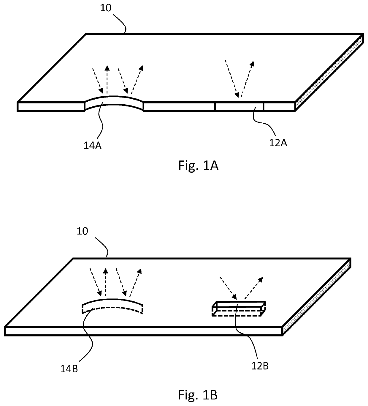
[0020]The invention is discussed below with the aid of embodiments in which the reflector surface is at each point thereof perpendicular to the waveguide plane and either planar or curved when seen in the waveguide plane. However, the same principles can be applied to such embodiments where the surface is tilted or curved in the cross-sectional plane of the waveguide. If tilted or curved, the tilting or curvature is moderate, meaning that the surface will not substantially out-couple propagating rays that hit the surface through the main surface of the waveguide, but redirects them between optical elements on the waveguide.

[0021]The change in angle distribution of light, i.e. the optical function of the reflector surface, is determined by the shape of the reflector surface and, in the case of grating-based or thin-film stack reflectors, the grating or thin-film structure.

[0022]With reference to FIGS. 1A and 1B, in some embodiments, there is provided a waveguide display element compr...


PUM


Abstract

The invention provides waveguide display element comprising a waveguide (10) comprising two opposing main surfaces, a first optical element arranged at a first location of the waveguide (10), a second optical element arranged at a second location of the waveguide (10), and at least one reflector surface (12A, 14A) extending between said main surfaces and adapted to reflect light rays propagating within the waveguide (10). The reflector surface (12A, 14A) is adapted to redirect light rays from the first optical element to the second optical element.

Description

FIELD OF THE INVENTION[0001]The invention relates to waveguide displays which can be used in personal display devices, such as head-mounted displays (HMDs) and head-up displays (HUDs). Such displays typically comprise a waveguide and at least one diffractive optical element, such as a grating, arranged onto or into the waveguide.BACKGROUND OF THE INVENTION[0002]Waveguides are key image-forming elements in many modern personal display devices. The image to be displayed can be coupled into and out of the waveguide, as well as modified within the waveguide, using diffractive gratings arranged in the main plane of the waveguide, typically on its surface. For example, there may be provided an in-coupling grating for coupling an image from a projector into the waveguide, an exit pupil expander (EPE) grating for expanding the light field in one or more in-plane dimensions of the waveguide, and an out-coupling grating which couples the light field out of the waveguide to the user's eye. Gra...

Claims


Application Information

Patent Timeline
IPC IPC(8): G02B27/01G02B27/00G02B27/42G02B5/18
CPCG02B27/0172G02B5/1819G02B27/4272G02B27/0081G02B2027/0123G02B2027/0125G02B2027/0174G02B5/1814G02B27/0101
Inventor BLOMSTEDT, KASIMIRERDMANIS, MIKHAIL
Owner DISPELIX OY
Why Eureka
Try Eureka