Turbofan engine plug dismounting method, dismounting tool and dismounting simulation device

A technology for a turbofan engine and a dismantling tool, which is used in the field of dismantling simulation devices and engine runner inspections, can solve problems such as difficulty in dismantling, inability to see external ducts, plugs, self-locking nuts or bushings, etc. The effect of small space occupation, convenient dismantling simulation operation, and simple dismantling method

Active Publication Date: 2022-07-29
CHINA HANGFA GUIZHOU LIYANG AVIATION POWER CO LTD
View PDF7 Cites 0 Cited by
  • Summary
  • Abstract
  • Description
  • Claims
  • Application Information

AI Technical Summary

Problems solved by technology

[0002] At present, when inspecting the flow path of a turbofan engine, it is necessary to remove the plug structure on the combustion chamber (turbine observation window) of the turbofan engine. Due to the cover of the outer casing, the situation in the outer duct cannot be seen during the removal operation (because Need to use hands or tools to enter the external duct), it can only be operated by experience and feeling, which makes it difficult to remove
In addition, the distance between the inner and outer walls of the outer duct is relatively large, and it is easy to drop the plug, self-locking nut or bushing into the outer duct of the engine when removing the plug

Method used


Image

  • Turbofan engine plug dismounting method, dismounting tool and dismounting simulation device
  • Turbofan engine plug dismounting method, dismounting tool and dismounting simulation device
  • Turbofan engine plug dismounting method, dismounting tool and dismounting simulation device

Examples


Embodiment Construction

[0035] The present invention will be further described below in conjunction with the accompanying drawings and specific embodiments, but it should not be construed that the scope of the subject matter of the present invention is limited to the following embodiments. Various modifications, substitutions and alterations made by common technical knowledge and conventional means are included within the scope of the present invention.

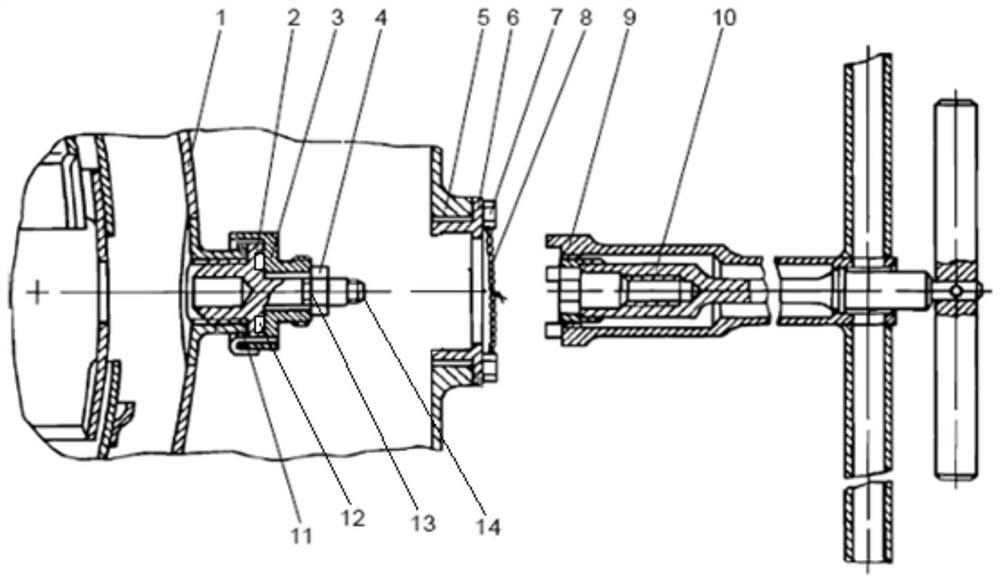
[0036] like image 3 As shown, the plug 2 is inserted into the inner hole of the boss mounting seat 11 of the combustion chamber casing 1, and a part of the structure of the plug 2 (the part connected with the self-locking nut 4 and the bushing 3) is located at In the outer duct of the turbofan engine between the combustion chamber casing 1 and the outer casing, the plug 2 is sleeved with a bushing 3, a gasket 13 and a self-locking nut 4, and the gasket 13 is located between the bushing 3 and the self-locking nut. 4, the outer surface of the bushin...


PUM


Abstract

The invention discloses a turbofan engine plug dismounting method, a dismounting tool and a dismounting simulation device.According to the dismounting method, under the condition that no view exists, a self-locking nut and a lining are dismounted firstly, then a plug is pulled out, tools used in the dismounting process comprise an outer sleeve and an inner sleeve, the inner sleeve is located in the outer sleeve, and the inner sleeve is located in the outer sleeve; the inner sleeve is provided with a thread matched with the thread of the plug and a surface matched with the self-locking nut, and the outer sleeve is provided with a thread matched with the thread of the bushing and a tenon structure matched with the groove of the plug. According to the dismounting simulation device, the hemispheroidal outer casing simulation housing is adopted to replace an outer casing, a blanking cap and a mounting base in a real engine, the simulation device is simplified, and meanwhile, the dismounting simulation process is facilitated. The plug dismounting method is simple and easy to implement, and workers can safely and reliably dismount the plug on the engine combustion chamber by using the dismounting tool under the condition that no view exists.

Description

technical field [0001] The invention belongs to the technical field of engine assembly, and relates to engine flow channel inspection, in particular to a removal tool, a removal method and a removal simulation device for a plug corresponding to an observation window on a casing. Background technique [0002] At present, when checking the flow passage of the turbofan engine, it is necessary to remove the plug structure on the combustion chamber (turbine observation window) of the turbofan engine. Due to the shielding of the outer casing, the situation in the outer duct cannot be seen during the removal operation (because It is necessary to enter the external duct by hand or tools), which can only be operated by experience and feeling, which makes it difficult to remove. In addition, the distance between the inner and outer walls corresponding to the outer duct is relatively large, and it is easy to drop the plug, self-locking nut or bushing into the outer duct of the engine w...

Claims


Application Information

Patent Timeline
Patent Type & Authority Applications(China)
IPC IPC(8): B25B27/02
CPCB25B27/02
Inventor 孙小平薛慧聪李超殷世伟方炳邹主兵刁海翔
Owner CHINA HANGFA GUIZHOU LIYANG AVIATION POWER CO LTD
Why Eureka
Try Eureka