
Process for mounting magnets in an electric motor rotor

a technology of magnets and electric motors, applied in the direction of magnetic circuit rotating parts, cage rotor manufacturing, magnetic circuit shape/form/construction, etc., can solve the problems of high cost and efficiency loss, and achieve the effect of maintaining the efficiency of the motor

Inactive Publication Date: 2011-03-01
WHIRPOOL SA
View PDF3 Cites 6 Cited by
  • Summary
  • Abstract
  • Description
  • Claims
  • Application Information

AI Technical Summary

Benefits of technology

[0007]Thus, it is an object of the present invention to provide a process for mounting magnets to an electric motor rotor, which besides maintaining the efficiency of the motor does not increase its cost and maintains the magnets housed in the interior of the rotor, which can thus be handled and mounted until the step of magnetizing the magnets.
[0008]It is a further object of the present invention to provide an electric motor rotor which can keep the permanent magnets housed in the interior of grooves provided in the lamination stack of the rotor core under operating conditions, in order to avoid that, eventually, said motor can have its magnetic field weakened or annulled.SUMMARY OF THE INVENTION

Problems solved by technology

While this solution avoids the involuntary escape of each permanent magnet in relation to its respective housing, it presents some inconveniences such as high cost and loss of efficiency when the end caps are made of electric steel, for example.

Method used


Image

  • Process for mounting magnets in an electric motor rotor
  • Process for mounting magnets in an electric motor rotor
  • Process for mounting magnets in an electric motor rotor

Examples


Embodiment Construction

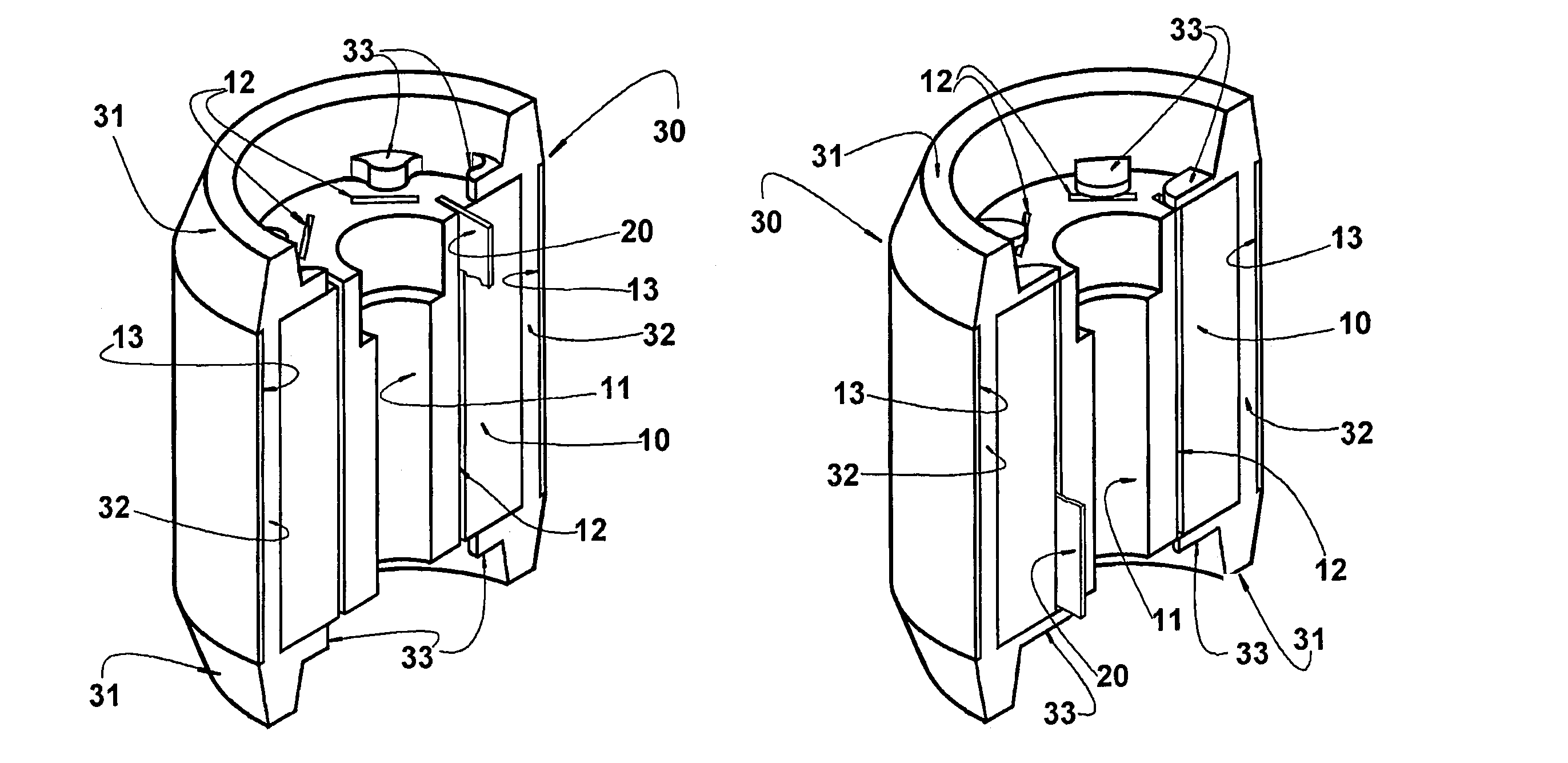
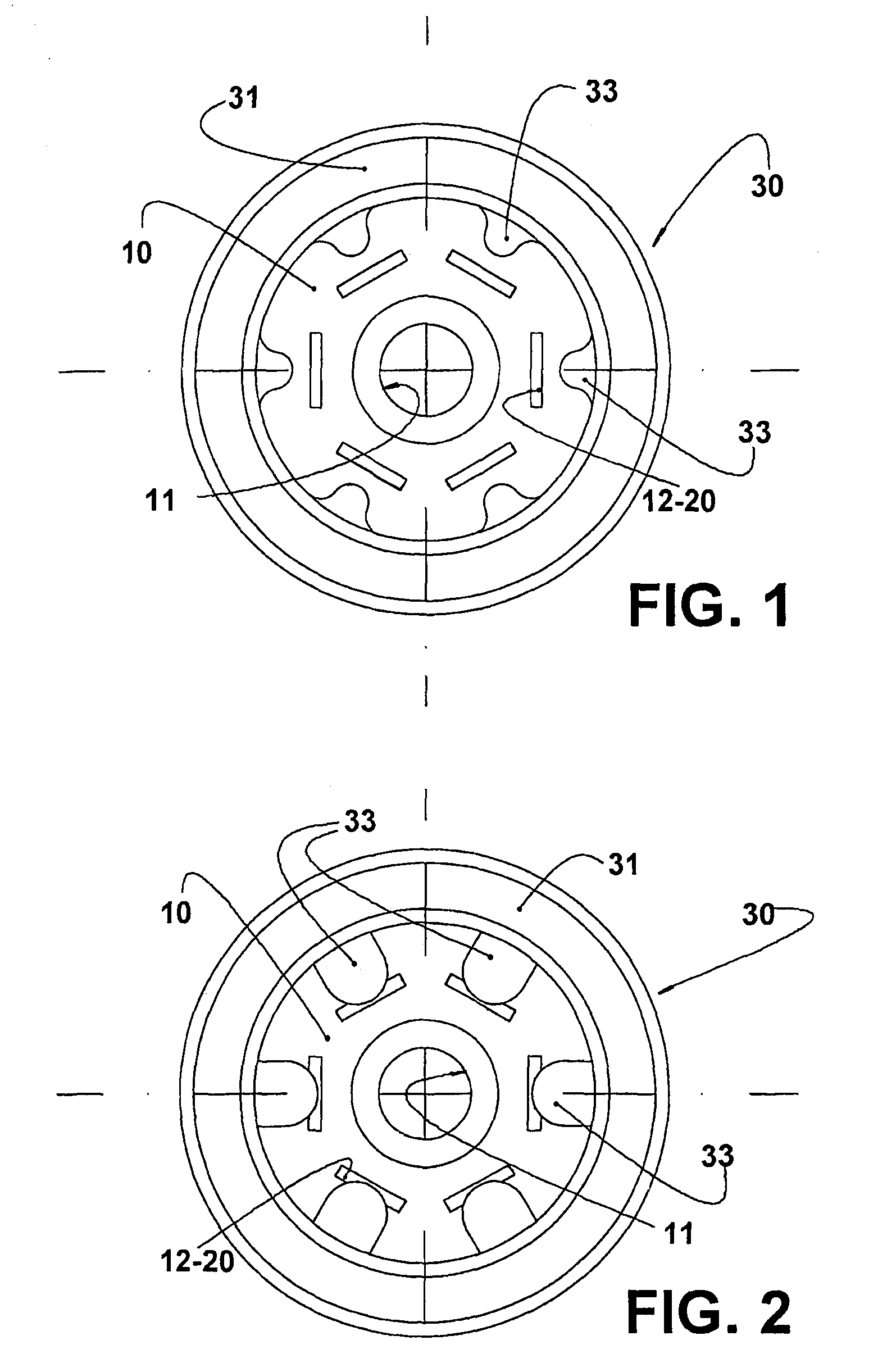
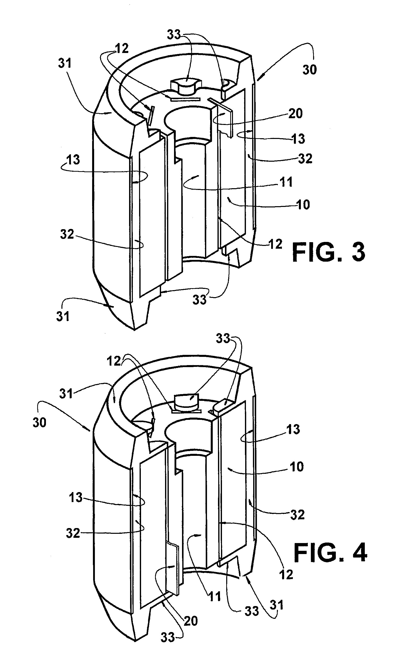
[0016]The present invention will be described in relation to an electric motor rotor of the type comprising a rotor core formed by a lamination stack 10 lodging permanent magnets 20, and a rotor cage 30 generally made of aluminum.

[0017]The lamination stack 10 of the rotor core is formed by a plurality of superposed steel annular laminations provided with openings longitudinally aligned with the openings of the other laminations of the stack, defining a central axial bore 11 in the lamination stack 10; a plurality of axial channels 12 disposed around the central axial bore 11, and axial bores 13 disposed in a peripheral portion of the lamination stack 10 external to the axial channels 12 that interconnect the external faces of the end laminations of the lamination stack 10. Each axial channel 12 is dimensioned to lodge at least one permanent magnet 20, said permanent magnets 20 defining the rotor poles.

[0018]The axial channels 12 are arranged angularly spaced from each other along a ...


PUM

PropertyMeasurementUnit
magnetic fieldaaaaaaaaaa

Abstract

A process for mounting magnets in an electric motor rotor and an electric motor rotor, said rotor comprising: a lamination stack (10) provided with a plurality of axial channels (12) disposed around a central axial bore (11) and housing permanent magnets (20); and a rotor cage (30) formed by a pair of end rings (31), each seated against an adjacent end lamination of the lamination stack (10) and interconnected by a plurality of bars (32), said process comprising the steps of: forming an end, ring (31) with at least one inner radial projection (33) disposed radially external to the projection of the contour of an axial channel (12); mounting in each axial channel (12) at least one permanent magnet (20); and deforming each inner radial projection (33) in order to increase its radial extension the sufficient to radially cover at least part of the projection of the contour of said axial channel (12), defining a stop for axially retaining the respective permanent magnet (20). The present invention further provides an electric motor rotor having the characteristics defined above.

Description

FIELD OF THE INVENTION[0001]The present invention refers to a process for mounting permanent magnets in housings formed in the lamination stack of the rotor and to an electric motor rotor, particularly the rotor of small electric motors of the synchronous type, such as those used in the hermetic compressors of small refrigeration systems.BACKGROUND OF THE INVENTION[0002]The rotors of synchronous electric motors are used in household appliances, such as refrigerators, freezers, air conditioners, hermetic compressors, laundry machines, pumps, fans, etc.[0003]Such motors are usually formed by a stator, a rotor and permanent magnets, said rotor being of the type formed by a rotor core, which carries the permanent magnets, and a rotor cage usually made of aluminum and formed by end rings connected to aluminum axial bars formed during a casting process of said rotor cage.[0004]The rotor core includes a stack of superposed annular steel laminations provided with openings longitudinally ali...

Claims


Application Information

Patent Timeline
Patent Type & Authority Patents(United States)
IPC IPC(8): H02K15/03H02K1/27H02K1/22H02K15/00
CPCH02K1/223H02K15/03H02K15/0012Y10T29/49012H02K1/27
Inventor LONGO, GELSONSTARKE, ORLANDOHILLE, ROBERTO CLAUDIOMOHR, JOSE WALTERRAMIREZ, ARTURO RIVIO
Owner WHIRPOOL SA
Learn More