Card reader device and method of use

a card reader and card reader technology, applied in the field of card reader devices, can solve the problems of hardly ever used, no way for an individual to take, and more expensive and complex decoding and communication components, and achieve the effects of simple construction and design, high reliability, and easy us

Inactive Publication Date: 2011-03-01
REM HLDG 3
View PDF15 Cites 150 Cited by
  • Summary
  • Abstract
  • Description
  • Claims
  • Application Information

AI Technical Summary

Benefits of technology

[0011]In light of the foregoing comments, it will be recognized that the present disclosure provides a card reader device comprised of a very simple external device to be used in conjunction with a host device having application software provided to perform the decoding function.
[0014]The present disclosure is directed to a card reader device that is of simple construction and design and which can be easily employed with highly reliable results.
[0015]The present disclosure is related to a card reader device that can be easily carried, transported, or stored.
[0019]The present disclosure also provides a card reader device that can operate with existing magnetic stripe cards without having to retrofit or change existing magnetic stripe cards.

Problems solved by technology

Conventional magnetic stripe card readers are comprised of both relatively simple sensing components as well as the more costly and complex decoding and communication components.
However, for the most part, the third track is hardly ever used.
Although magnetic stripe cards are universally used by merchants there is no way for an individual to take advantage of the card to receive a payment from another individual (who is not a merchant) by swiping the card through a simple reader attached to his cell phone or another device which can connect to the Internet.
However, there is presently no way for an individual to send payment to an individual or merchant through the use of a magnetic stripe card by using a simple magnetic stripe card reader connected to a cell phone or other device.

Method used


Image

  • Card reader device and method of use
  • Card reader device and method of use
  • Card reader device and method of use

Examples


Embodiment Construction

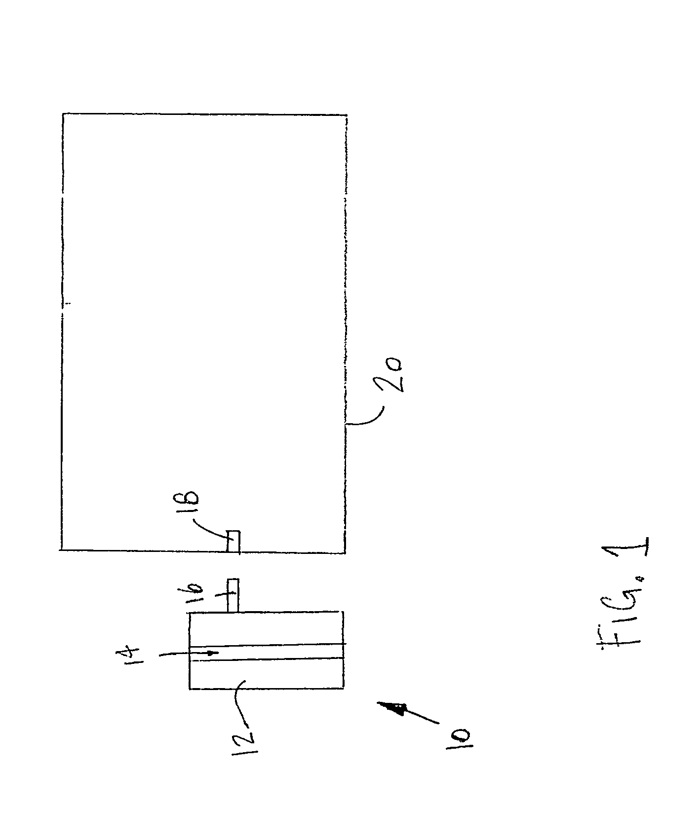
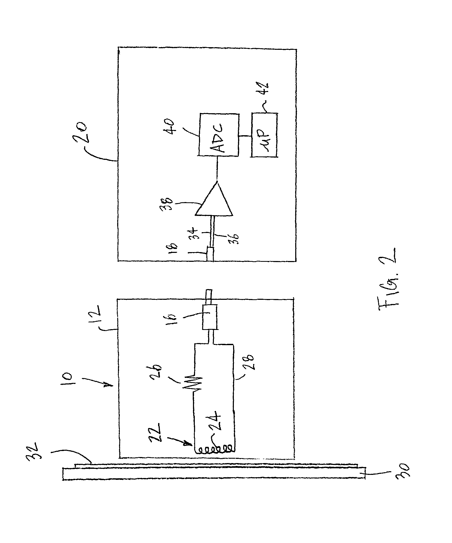
[0029]Referring now to the drawings, wherein like numbers refer to like items, number 10 identifies a preferred embodiment of a card reader device constructed according to the present disclosure. With reference now to FIG. 1, the card reader device 10 is shown to comprise a housing 12 having a slot 14 and an output jack 16 extending out from the housing 12. The jack 16 is adapted to be inserted into a socket 18 such as a microphone input or a line in audio input of a cell phone 20. It is also possible and contemplated that the jack 16 may be inserted into a socket associated with other devices such as an iPod touch, a personal digital assistant (PDA), or a device that has WiFi (wireless fidelity) connectivity. The jack 16 may be a TRS (tip, ring, sleeve) connector also known as an audio jack, phone plug, jack plug, stereo plug, mini-jack, or mini-stereo audio connector. The jack 16 may be formed of different sizes such as miniaturized versions that are 3.5 mm or 2.5 mm. It is also p...


PUM


Abstract

A card reader device for reading a card having data stored on a magnetic stripe incorporated into the card is disclosed in which the card reader device comprises a read head for passing a magnetic stripe of a card by to read data stored on a magnetic stripe and for producing a signal indicative of data stored on a magnetic stripe, a signal setting device for setting an amplitude of the signal indicative of data stored on a magnetic stripe, and an output plug adapted to be inserted into a headset jack associated with a host device for providing the signal indicative of data stored on a magnetic stripe to a host device.

Description

RELATED APPLICATION[0001]This application is a continuation-in-part application of U.S. patent application Ser. No. 12 / 456,134, which was filed on Jun. 10, 2009 now U.S. Pat. No. 7,810,729.BACKGROUND[0002]This disclosure relates to a card reader device for use with a host device for reading a magnetic stripe card and more particularly to a portable card reader device which senses the magnetically recorded information stored on a magnetic stripe card and conveys this sensed information via an analog waveform to a host device for further processing.[0003]Plastic cards having a magnetic stripe embedded on one side of the card are prevalent in every day commerce. These cards are used in various transactions such as to pay for purchases by using a credit card, a debit card, or a gasoline charge card. A charge card or a debit card may also be used to transact business with a bank through use of an automated teller machine (ATM). The magnetic stripe card is capable of storing data by modif...

Claims


Application Information

Patent Timeline
Patent Type & Authority Patents(United States)
IPC IPC(8): G06K7/08G06K7/00H04M1/72409H04M1/72412
CPCG06K7/083H04M1/72527H04M2250/14H04M1/72409H04M1/72412G06K7/08
Inventor MORLEY, JR., ROBERT E.
Owner REM HLDG 3
Why Eureka
Try Eureka