System and method for monitoring periodic breathing associated with heart failure

a technology of heart failure and monitoring system, applied in the field of implantable and external devices, can solve problems such as failure of the brain to send appropriate signals

Active Publication Date: 2011-03-01
MEDTRONIC INC
View PDF20 Cites 32 Cited by
  • Summary
  • Abstract
  • Description
  • Claims
  • Application Information

AI Technical Summary

Problems solved by technology

Instead, CSA involves failure of the brain to send appropriate signals to initiate action of the muscles required for respiration.

Method used


Image

  • System and method for monitoring periodic breathing associated with heart failure
  • System and method for monitoring periodic breathing associated with heart failure
  • System and method for monitoring periodic breathing associated with heart failure

Examples


Embodiment Construction

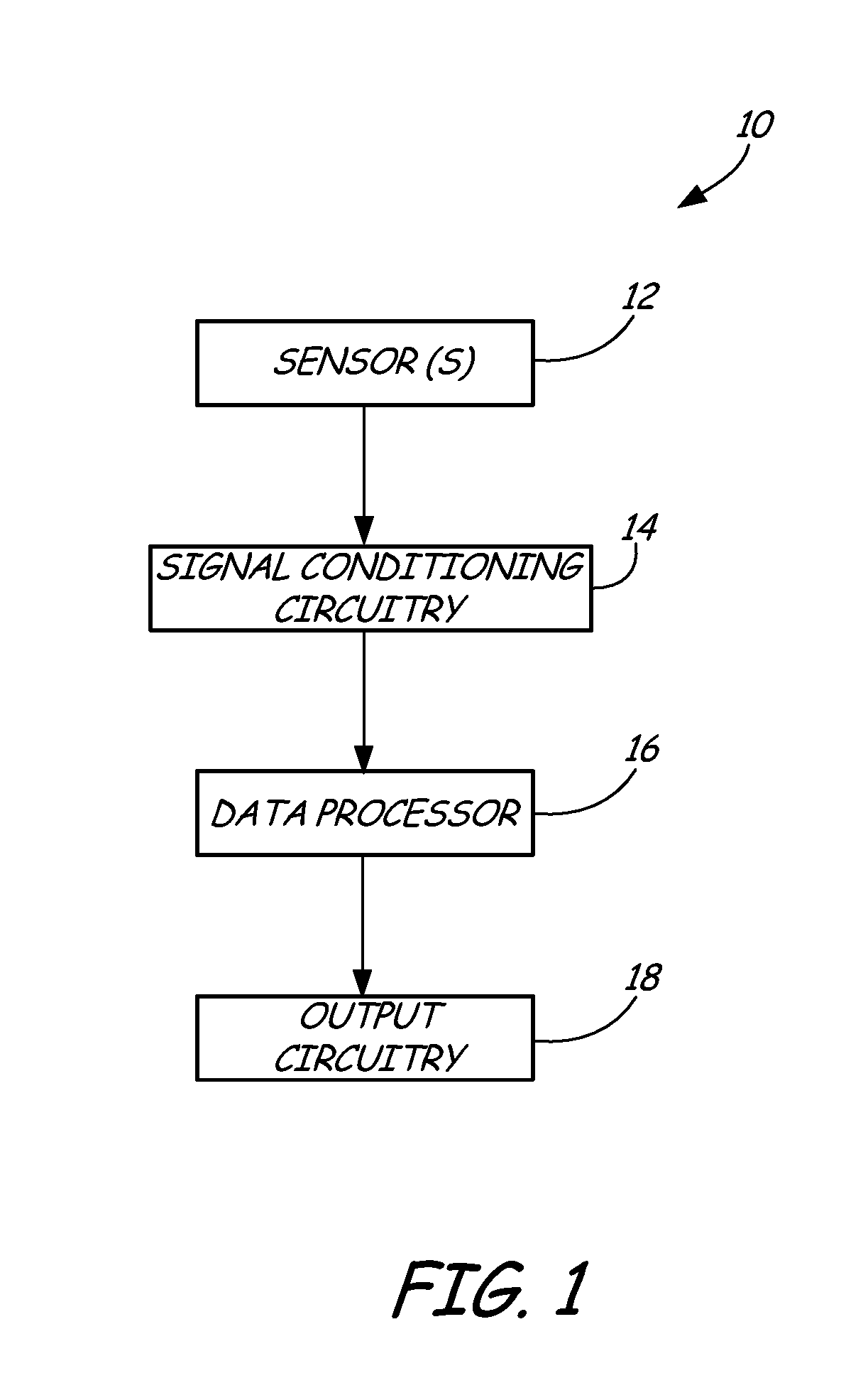
[0012]FIG. 1 shows a block diagram representation of a monitoring device of the present invention for detecting and monitoring periodic breathing. As shown in FIG. 1, periodic breathing monitor 10 includes one or more sensors 12, signal conditioning circuitry 14, data processor 16, and output circuitry 18. Sensor(s) 12 produce sensor signals representative of one or more physiologic parameters associated with respiration of a patient. Sensor(s) 12 are in communication with signal conditioning circuitry 14, which conditions sensor signals received from sensor(s) 12 for transmittal to data processor 16. Data processor 16 monitors the conditioned sensor signals and produces a biomarker output as a function of the condition sensor signals. The biomarker output may be stored and / or communicated to output circuitry 18 for transmittal to a remote location for further processing, storage, and / or communication to a healthcare provider or patient.

[0013]Monitor 10 may be an implantable device ...


PUM


Abstract

A system and method for monitoring in a patient includes producing sensor signals representative of a physiologic parameter associated with respiration. A periodic breathing cycle is detected based on the sensor signals. An output is produced as a function of the cycle length.

Description

BACKGROUND OF THE INVENTION[0001]The present invention relates generally to implantable and external devices for monitoring physiologic parameters associated with respiration. In particular, the present invention relates to monitoring periodic breathing, such as central sleep apnea, as an indicator or biomarker of congestive heart failure.[0002]Sleep apnea is generally defined as a cessation of breathing during sleep, and can typically be categorized as one of two basic types: central sleep apnea (CSA) or obstructive sleep apnea (OSA). OSA is the more common type of sleep apnea, and is generally characterized by repetitive pauses in breathing during sleep due to the obstruction and / or collapse of the upper airway. CSA is an apnea that is neurally mediated. The apnea is caused by neural signaling (or lack thereof) causing cessation of substantially all respiratory effort during sleep, usually accompanied with decreases in blood oxygen saturation (SaO2).[0003]Unlike OSA, CSA does not ...

Claims


Application Information

Patent Timeline
Patent Type & Authority Patents(United States)
IPC IPC(8): A61B5/08
CPCA61B5/08A61B5/4818A61B5/021A61B5/087A61B5/1135A61B5/1455A61B7/003G16H40/63G16H50/20
Inventor SOWELAM, SAMEHMARKOWITZ, H. TOBYERICKSON, MARK K.NICOLAESCU, IOANA
Owner MEDTRONIC INC
Why Eureka
Try Eureka