Coil component

a coil and component technology, applied in the direction of coils, transformers/inductance details, inductances, etc., can solve the problems of dc bias characteristics that are not well-defined, and achieve the effect of preserving good inductance characteristics and enhancing dc bias characteristics

Active Publication Date: 2011-03-01
TDK CORPARATION
View PDF22 Cites 19 Cited by
  • Summary
  • Abstract
  • Description
  • Claims
  • Application Information

AI Technical Summary

Benefits of technology

[0008]In the present invention, the magnetic flux generated in the coil formed by the winding passes thus through the first cover portion between the first and second flanges. This keeps hence leakage flux small, affording thus good inductance characteristics.
[0018]The present invention allows thus providing a coil component that enhances DC bias characteristics while preserving good inductance characteristics.

Problems solved by technology

A closed magnetic circuit, however, is problematic in that magnetic saturation is likely to occur in the circuit, impairing DC bias characteristics.

Method used


Image

  • Coil component
  • Coil component
  • Coil component

Examples


Embodiment Construction

[0030]Preferred embodiments of the present invention are explained in detail below with reference to accompanying drawings. In the drawings, identical elements are denoted with identical reference numerals, and recurrent explanations thereof are omitted.

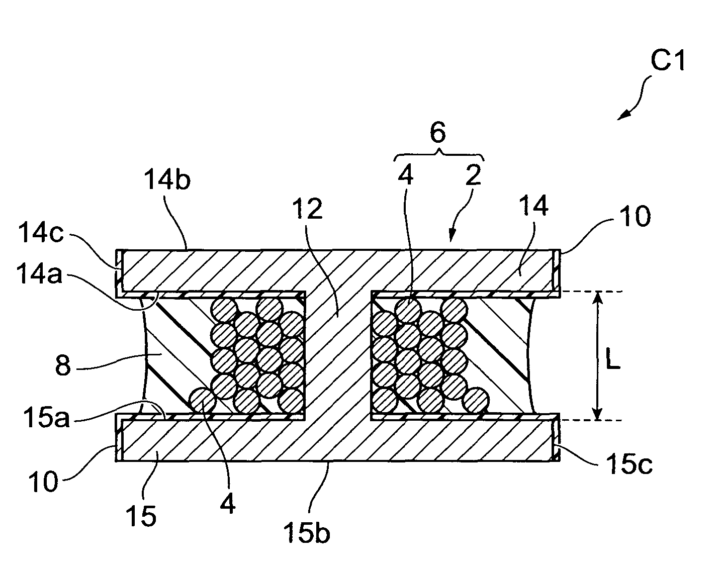
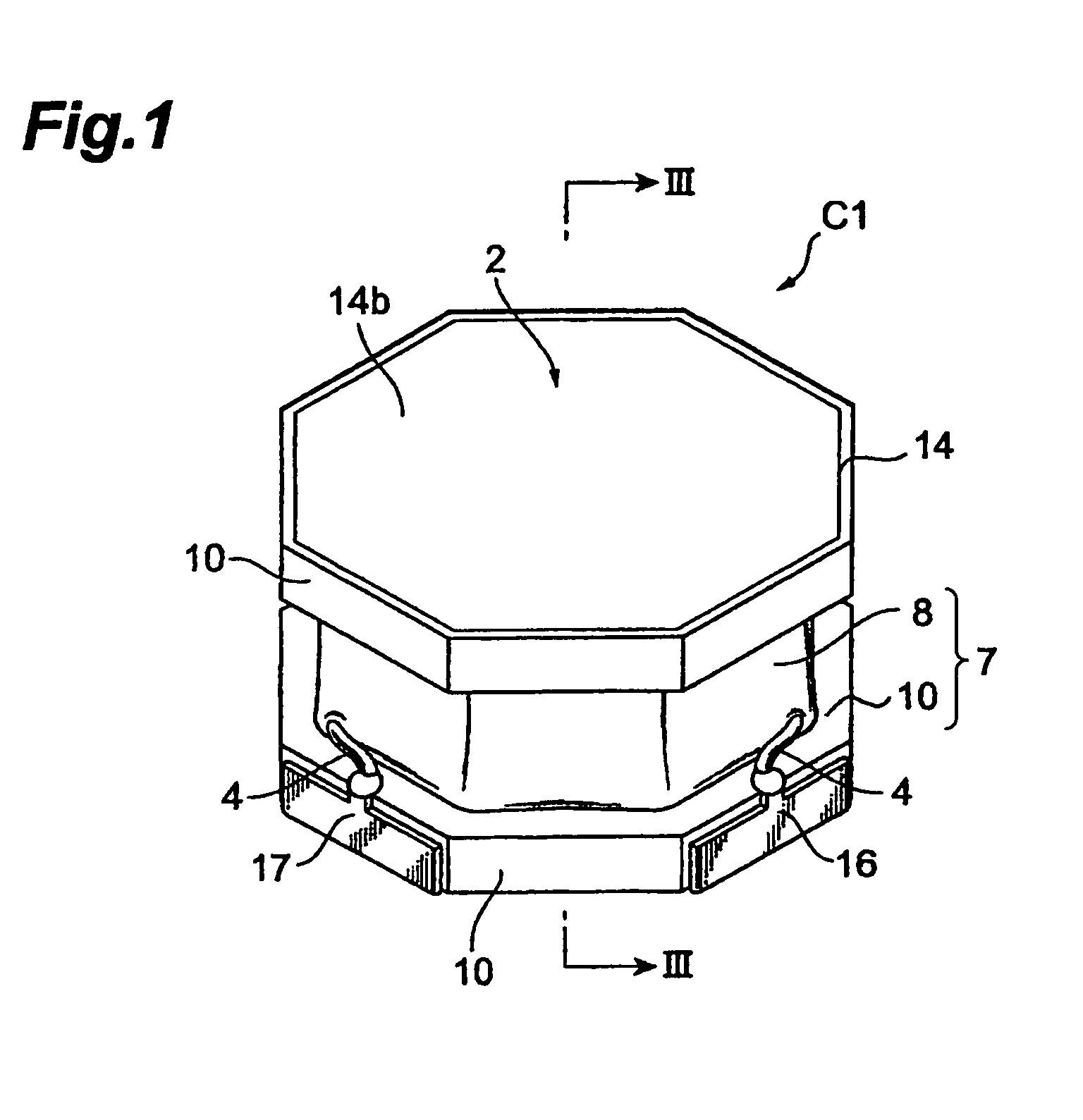
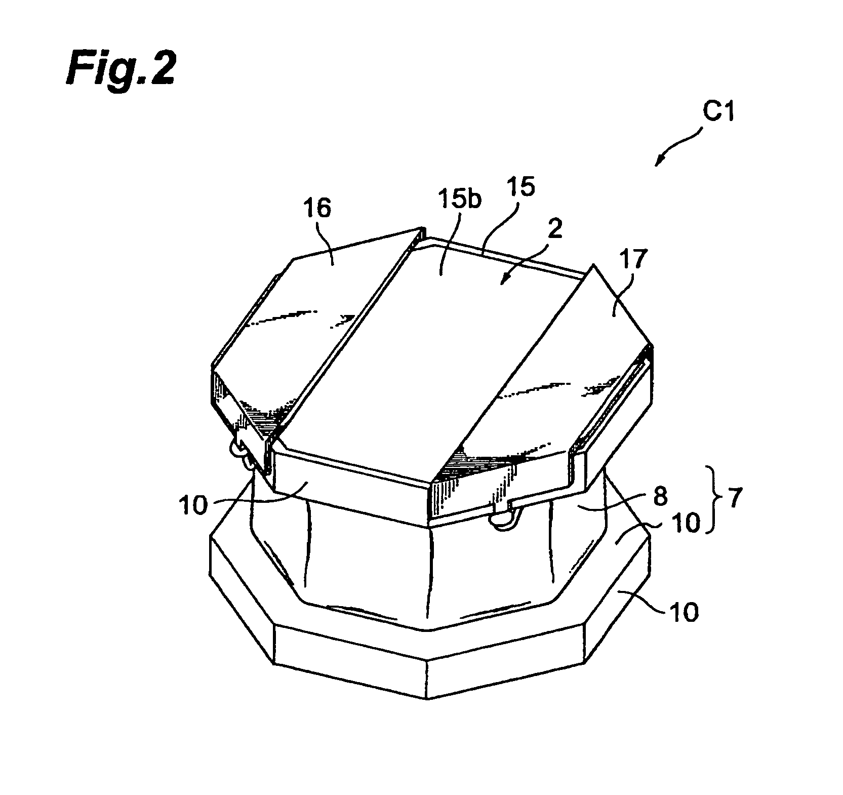
[0031]FIGS. 1 and 2 are perspective-view diagrams illustrating a coil component according to the present embodiment. FIG. 3 is a diagram illustrating schematically the cross-sectional structure of the coil component illustrated in FIG. 1 along the III-III direction. As shown in the figures, a coil component C1 comprises a core 2, a winding 4 and a cover portion 7.

[0032]As illustrated in FIG. 3, the core 2 has a columnar winding core portion 12, and a pair of flanges 14, 15 arranged at both ends of the axial direction of the winding core portion 12. The pair of flanges 14, 15 is shaped so that the outer periphery of the flanges protrudes out of the winding core portion 12, with the flanges arranged substantially parallel to each other...


PUM

PropertyMeasurementUnit
densityaaaaaaaaaa
thicknessaaaaaaaaaa
distanceaaaaaaaaaa

Abstract

A coil component comprises: a core having a winding core portion, and a first flange and a second flange arranged at both ends of the winding core portion; a winding arranged in a region flanked by the first and second flanges, and wound so as to be in contact with the winding core portion; and a cover portion arranged in a region flanked by the first and second flanges, so as to cover the winding. The cover portion has a first cover portion comprising a resin cured product containing a magnetic material; and a second cover portion comprising a non-magnetic material. The second cover portion is interposed at least between the first flange and the first cover portion.

Description

BACKGROUND OF THE INVENTION[0001]1. Field of the Invention[0002]The present invention relates to a coil component, and more particularly to a winding-type coil component.[0003]2. Related Background Art[0004]Known such coil components comprise a core (so-called drum-type core) having a winding core portion and a pair of flanges arranged at both ends of the winding core portion, a winding wound on the winding core portion, and a cladding resin containing a magnetic powder, filling the space between the pair of flanges (for instance, Japanese Unexamined Patent Application Laid-open No. 2005-210055). The cladding resin containing a magnetic powder covers the winding at a position between the pair of flanges.[0005]In the coil component described in Japanese Unexamined Patent Application Laid-open No. 2005-210055, the flux generated by the coil formed by the winding constitutes a magnetic circuit that extends from the winding core portion, via one flange, the cladding resin containing a m...

Claims


Application Information

Patent Timeline
Patent Type & Authority Patents(United States)
IPC IPC(8): H01F27/02H01F27/30H01F27/29
CPCH01F17/045H01F2017/048
Inventor KITAJIMA, YOSHIAKISHINDOH, MASATOSHI
Owner TDK CORPARATION
Why Eureka
Try Eureka