Coreless and brushless direct-current motor, Gifford McMahon (GM) cryogenic cooler, pulse tube cryogenic cooler, cryopump, Magnetic Resonance Imaging (MRI) apparatus, Superconducting Magnet (SCM) apparatus, Nuclear Magnetic Resonance (NMR) apparatus, and cryogenic cooler for cooling semiconductor

a direct-current motor and brushless technology, applied in the direction of magnetic resonance imaging (mri) apparatus, superconducting magnet (scm) apparatus, cryogenic coolers for cooling semiconductors, etc., can solve problems such as contamination

Inactive Publication Date: 2008-01-31
SUMITOMO HEAVY IND LTD
View PDF4 Cites 16 Cited by
  • Summary
  • Abstract
  • Description
  • Claims
  • Application Information

AI Technical Summary

Benefits of technology

[0009]Accordingly, embodiments of the present invention may provide a novel and useful coreless and brushless direct-current motor, Gifford McMahon (GM) cryogenic cooler, pulse tube cryogenic cooler, cryopump, Magnetic Resona...

Problems solved by technology

In addition, when an electric motor is used as a driving source, contaminants are gene...

Method used


Image

  • Coreless and brushless direct-current motor, Gifford McMahon (GM) cryogenic cooler, pulse tube cryogenic cooler, cryopump, Magnetic Resonance Imaging (MRI) apparatus, Superconducting Magnet (SCM) apparatus, Nuclear Magnetic Resonance (NMR) apparatus, and cryogenic cooler for cooling semiconductor
  • Coreless and brushless direct-current motor, Gifford McMahon (GM) cryogenic cooler, pulse tube cryogenic cooler, cryopump, Magnetic Resonance Imaging (MRI) apparatus, Superconducting Magnet (SCM) apparatus, Nuclear Magnetic Resonance (NMR) apparatus, and cryogenic cooler for cooling semiconductor
  • Coreless and brushless direct-current motor, Gifford McMahon (GM) cryogenic cooler, pulse tube cryogenic cooler, cryopump, Magnetic Resonance Imaging (MRI) apparatus, Superconducting Magnet (SCM) apparatus, Nuclear Magnetic Resonance (NMR) apparatus, and cryogenic cooler for cooling semiconductor

Examples


first embodiment

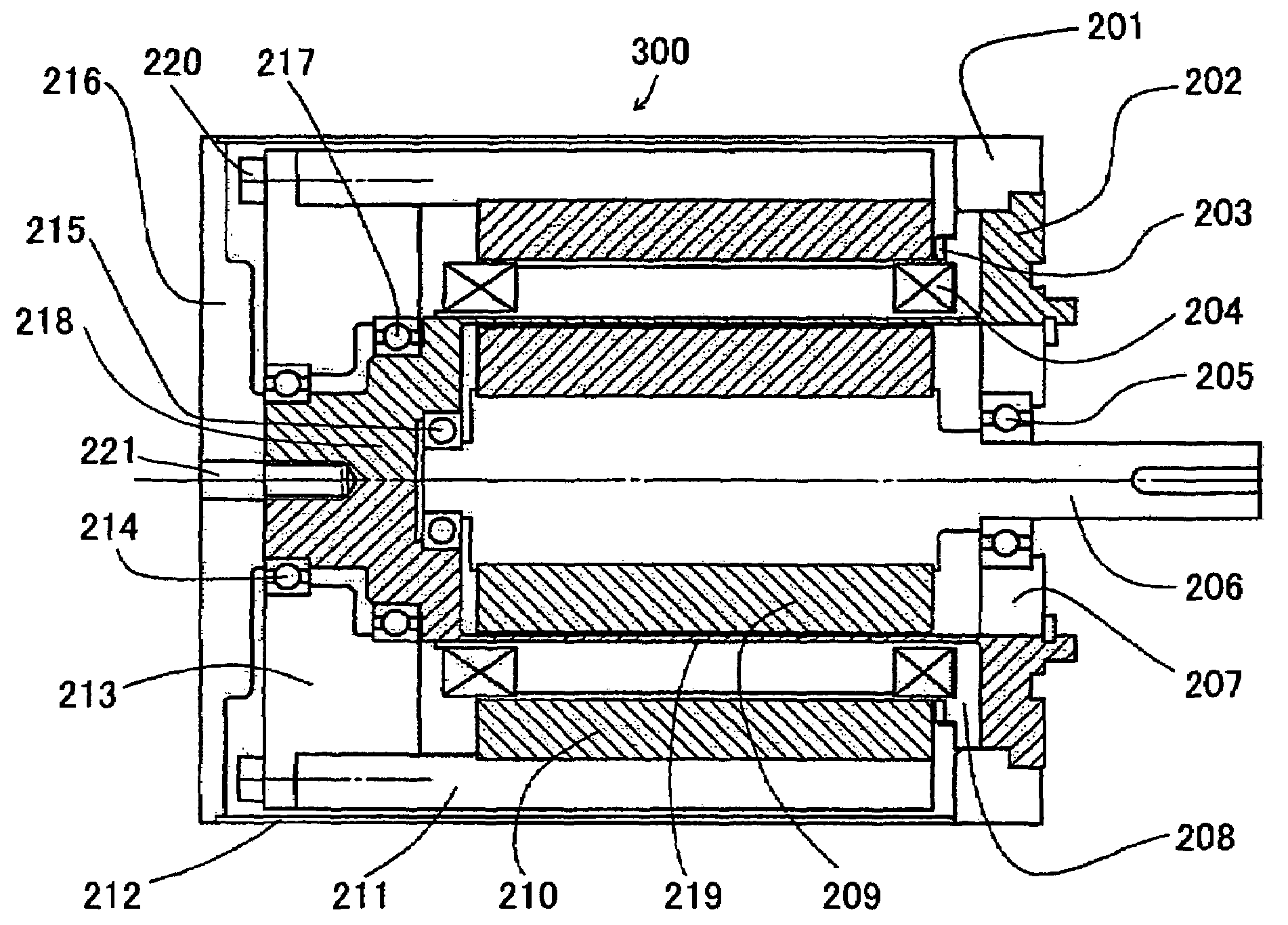
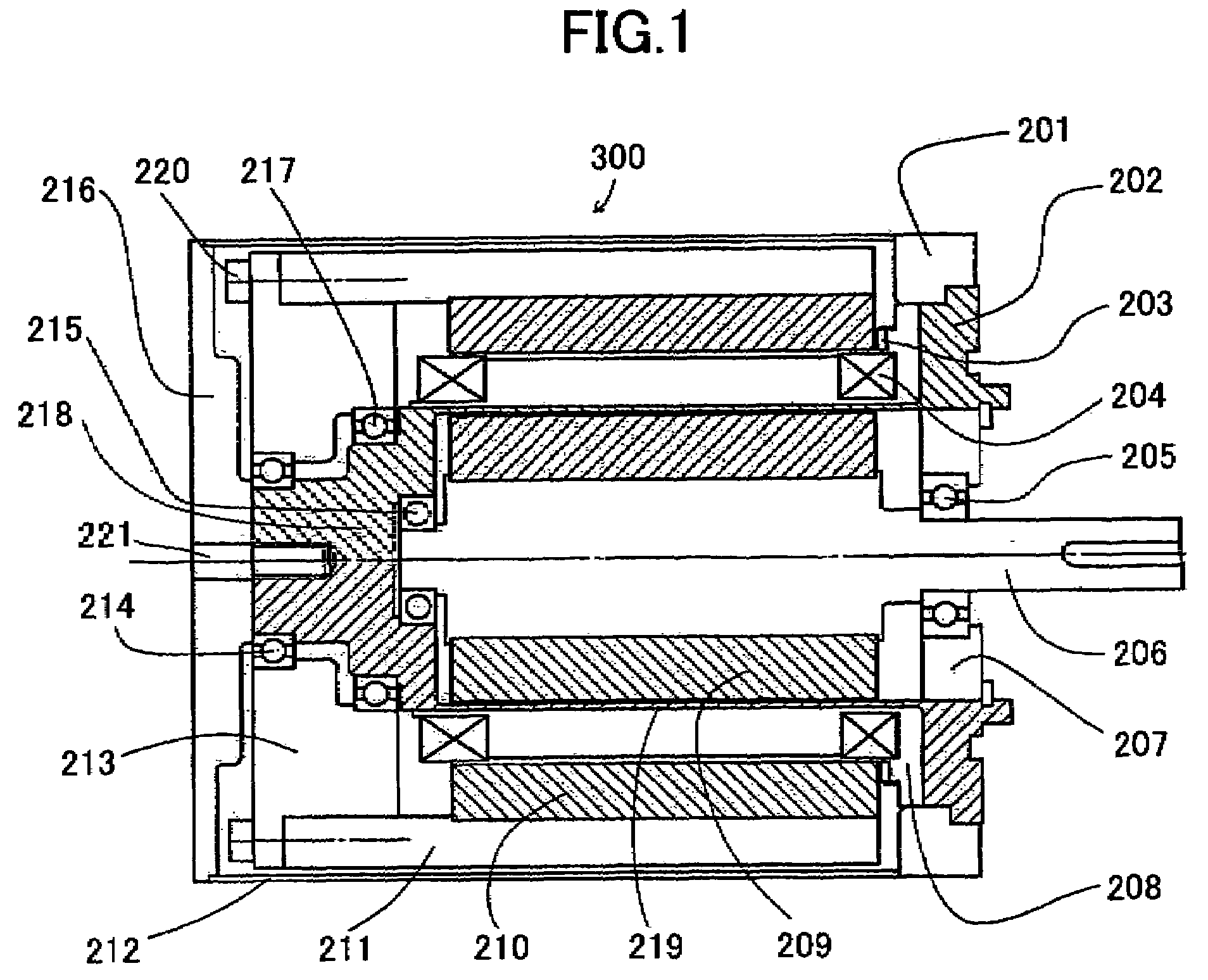
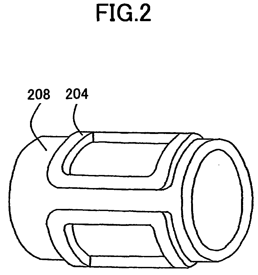
[0050]FIG. 1 is a cross-sectional view of a coreless and brushless direct-current motor of a first embodiment of the present invention. FIG. 2 is a perspective view of a saddle type armature coil attaching part forming the coreless and brushless direct-current motor of the first embodiment of the present invention.

[0051]Referring to FIG. 1 and FIG. 2, a coreless and brushless direct-current motor 300 of a first embodiment of the present invention has an armature coil 204 wound without core on a barrier part 219 and a coil holder 208. One end of a housing 218 is extended to the barrier part 219. The coil holder 208 is connected to a casing 202 and the barrier part 219. The armature coil 204 is formed in the shape of a saddle and includes plural coils separately provided on the outer surface of a cylindrical circumference.

[0052]When a direct current is applied to the armature coil 204, a magnetic field is generated. Because of this, there is no over current loss or hysteresis loss and...

second embodiment

[0082]FIG. 3 is a cross-sectional view of a coreless and brushless direct-current motor of a second embodiment of the present invention.

[0083]Referring to FIG. 3, a flat armature coil 35 of a coreless and brushless direct-current motor of a second embodiment of the present invention has a coreless coil wound in a ring shape. Plural flat armature coils 35 are provided in a cylindrical circumference shape on a board 41 surface connected to a barrier part 33 to which one end of a housing 46 is extended.

[0084]When a direct current is applied to the flat armature coil 35, a magnetic field is generated. Because of this, there is no over current loss and hysteresis loss and it is possible to maintain high electric motor efficiency.

[0085]The thickness of the coreless coil can be made less than the original coil external diameter. Hence, it is possible to easily correspond to limitations of lay-out of an inside of the electric motor. In addition, the coreless coil can be formed by stacking c...

third embodiment

[0112]FIG. 4 is a partial cross-sectional view of a Gifford McMahon (GM) cryogenic cooler having the coreless and brushless direct-current motor 300 of the embodiment of the present invention as a power unit.

[0113]In this embodiment, the present invention is applied to the GM cryogenic cooler which requires a barrier for preventing the entrance of contaminates.

[0114]The GM cryogenic cooler is used for cooling a cryopump or a superconducting MRI (Magnetic Resonance Imaging) Apparatus. In the GM cryogenic cooler, a compressor and an expansion unit are separately provided. Hence, while a small size compressor is operated at a high speed, the expansion unit is operated at a low speed.

[0115]The compressor 74 absorbs operation gas from a low pressure side and discharges the gas to a high pressure side. The cryogenic cooler can be divided into a housing part 60 and a cylinder part 61. A displacer 64 where a cool storage device 63 is installed is slidably provided at a cylinder 62 arranged ...


PUM


Abstract

A coreless and brushless direct-current motor includes an armature coil wound without core and formed in the shape of a saddle; an outside rotor magnet formed by a permanent magnet, the outside rotor magnet being provided at an outside of the armature coil in the shape of a cylinder so as to face the armature coil, the outside rotor magnet being rotated by the magnetic field; an inside rotor magnet formed by a permanent magnet, the inside rotor magnet being provided in the shape of a cylinder at an inside of the armature coil so that the inside rotor magnet has a pole opposite to the outside rotor magnet and a rotational shaft is independently provided; an output shaft connected to the inside rotor magnet; and a sealing part of a barrier structure which sealing part partitions the armature coil and the outside rotor magnet to an outside of the inside rotor magnet and seals the armature coil and the outside rotor magnet.

Description

BACKGROUND OF THE INVENTION[0001]1. Field of the Invention[0002]The present invention generally relates to coreless and brushless direct-current motors, Gifford McMahon (GM) cryogenic coolers, pulse tube cryogenic coolers, cryopumps, Magnetic Resonance Imaging (MRI) apparatuses, Superconducting Magnet (SCM) apparatuses, Nuclear Magnetic Resonance (NMR) apparatus, and cryogenic coolers for cooling semiconductors.[0003]More particularly, the present invention relates to a coreless and brushless direct-current motor used as a power source of a Stirling type cryogenic cooler or the like. The Stirling type cooler is used for a closed circuit cooling system or the like and has a sealing container that receives an expansion unit and a compressor, a GM cryogenic cooler, a pulse tube cryogenic cooler, a cryopump, a MRI apparatus, a SCM apparatus, an NMR apparatus, and a cryogenic cooler for cooling a semiconductor having the coreless and brushless direct-current motor as a power unit.[0004]2...

Claims


Application Information

Patent Timeline
IPC IPC(8): H02K5/16H02K21/12
CPCH02K5/128H02K21/12H02K16/02
Inventor KOIZUMI, TATSUOKOYAMA, TOMOHIROTAKAHASHI, TERUOISHIKAWA, MAKOTO
Owner SUMITOMO HEAVY IND LTD
Why Eureka
Try Eureka