Electrohydraulic control device

a control device and electrohydraulic technology, applied in the direction of valve operating device/release device, servomotor, transportation and packaging, etc., can solve the problem of easy oscillation, easy interference with the proportional work function of the check valve, seat valve body,

Inactive Publication Date: 2001-04-24
ROBERT BOSCH GMBH
View PDF3 Cites 18 Cited by
  • Summary
  • Abstract
  • Description
  • Claims
  • Application Information

AI Technical Summary

Problems solved by technology

It is disadvantageous in connection with this control device that only a 2/3 valve function can be represented, wherein no additional valve functions can be performed by the lowering element designed in accordance with seat valve techniques.
The volume flow appearing during the lowering of a load is here only controlled by a valve cone at a seat valve body, so that the flow forces appearing particularly at high loads can considerably interfere with the proportional work functioning of the check valve.
Therefore the seat valve body, which here is controlled purely hydraulically, easily tends to oscillate, particularly when

Method used


Image

  • Electrohydraulic control device
  • Electrohydraulic control device
  • Electrohydraulic control device

Examples


Embodiment Construction

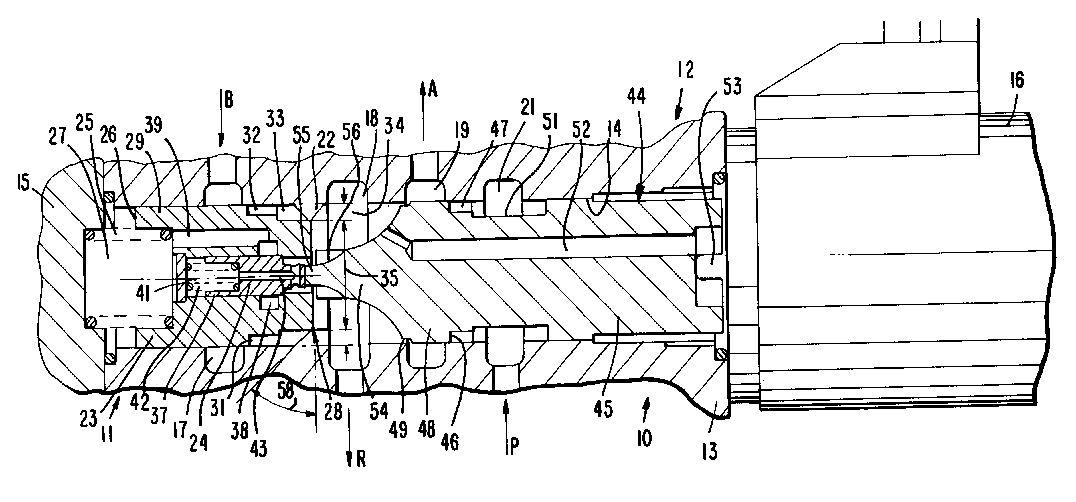
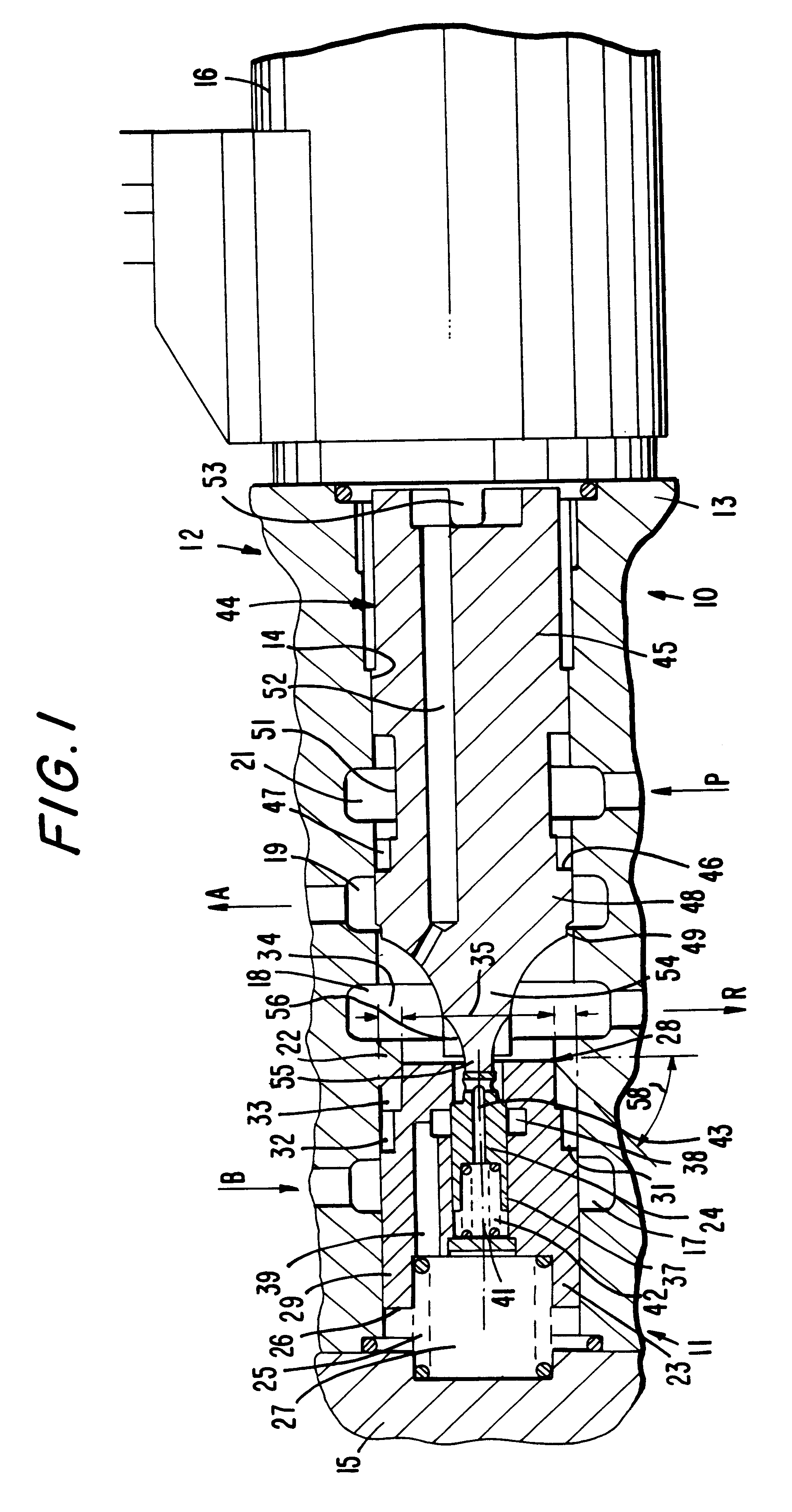
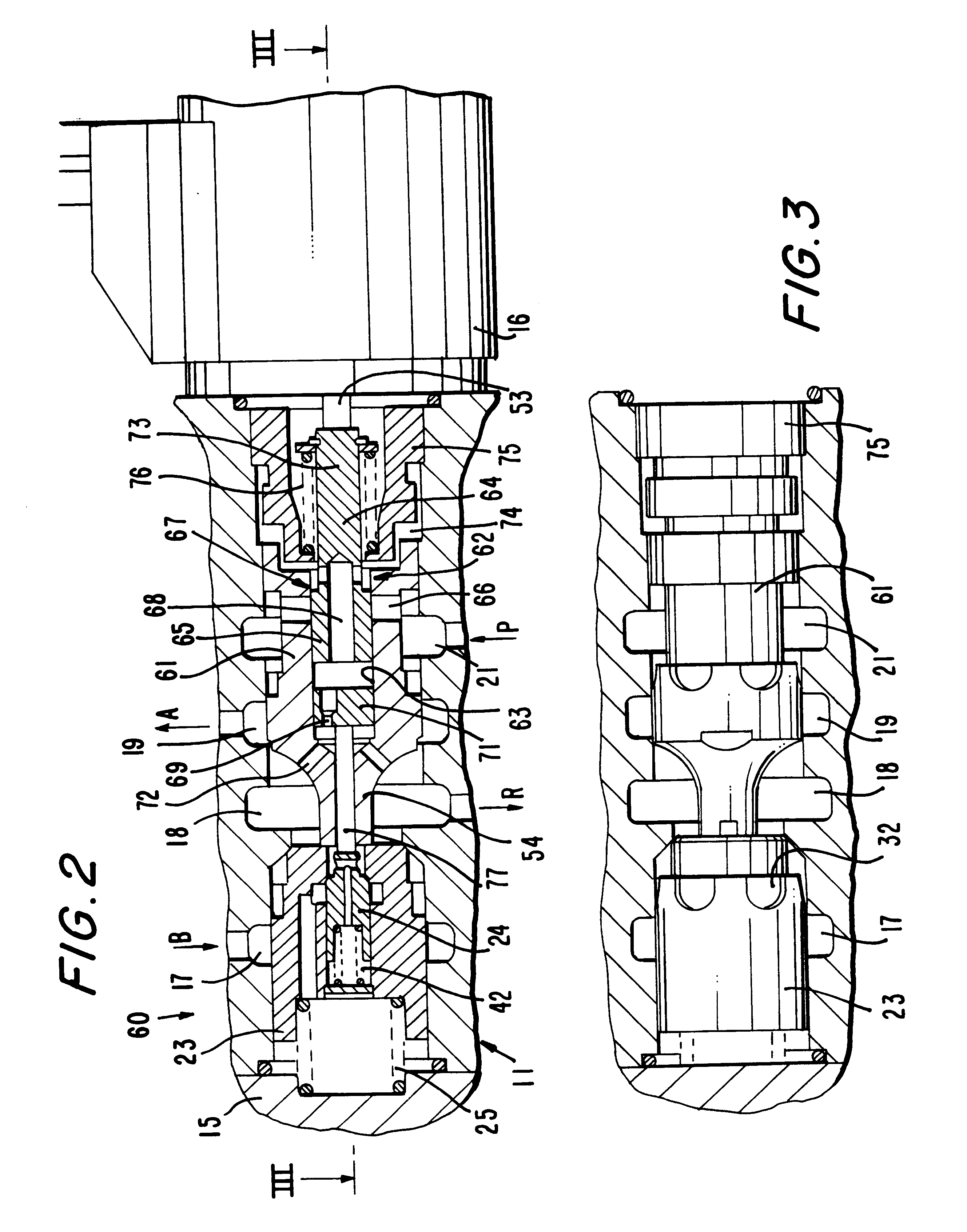
FIG. 1 shows a longitudinal section through a first electro-hydraulic control device 10 in a simplified representation, such as can be used for a hydraulic servo motor for the control of volume flows. The control device 10 is embodied as a 4 / 2 valve module, wherein a lowering element 11 produced in accordance with seat valve technology and a lifting element 12 produced in accordance with slide technology are combined with each other.

In a housing 13, the control device 10 has a continuous slide bore 14, which is closed at its front faces by a cover 15 and a proportional magnet 16. Chambers are formed in the slide bore 14 by means of ring-shaped widenings placed next to each other and embodied in the direction starting at the cover 15 and viewed in the direction toward the proportional magnet 16 as a first motor chamber 17, a return flow chamber 18, a second motor chamber 19 and in inflow chamber 21. A first motor connection B, a return connection R, a second motor connection A and an...


PUM


Abstract

An electro-hydraulic control device (10, 60) for a hydraulic servo motor for controlling a volume flow is proposed, which is embodied as a 4/2 valve module. A blocking valve in accordance with seat valve technology between a motor connection (B) and a return flow (R) form a lowering element (11), while the associated unblocking member (44) is designed as a longitudinal slide (45), which controls the connection between an inflow connection (P) and a motor connection (A) and is actuated by a proportional magnet (16). After unblocking the blocking valve, its seat valve body (23) is mechanically taken along by the longitudinal slide (45), and the two volume flows are proportionally controlled via the lowering element (11) and the lifting element (12), so that a large switching capacity is achieved along with a construction with few leaks.

Description

1. Field of the InventionThe invention is based on an electro-hydraulic control device and, more particularly, to an electro-hydraulic control device for a hydraulic servo motor for controlling a volume flow, having a blocking valve arranged in a housing, whose movable seat valve body is inserted into a connection between a motor chamber and a return flow chamber for securing the motor chamber, and having a proportional magnet with an armature-actuated tappet for actuating the blocking valve.2. Prior ArtThis type of electro-hydraulic control device is already known from U.S. Pat. No. 3,667,722, by means of which a delicate proportional volume control is possible. The check valve protecting the hydraulic servo motor with its load is here designed as a pilot seat valve, so that the leakage is as small as possible. This control device can be used as a lowering brake valve, wherein the actuating forces are as low as possible and therefore the proportional magnet can be made small. It is...

Claims


Application Information

Patent Timeline
IPC IPC(8): F15B13/01F15B11/00F15B13/043F15B13/00B62D5/09F15B13/044F16K11/07F16K31/06
CPCF15B11/003F15B13/01F15B13/043F15B2211/20553F15B2211/3051F15B2211/3057F15B2211/3144F15B2211/31576F15B2211/327F15B2211/6054Y10T137/87217Y10T137/87241
Inventor SANDAU, HARTMUTSCHUMACHER, WERNERLUEUES, HOLGER
Owner ROBERT BOSCH GMBH
Why Eureka
Try Eureka