Valve for Wellbore Applications

a valve and wellbore technology, applied in the direction of wellbore/well accessories, engine components, mechanical equipment, etc., can solve the problems of large differential pressure, high risk of damage on the formation, and high pressure on geothermal applications, so as to reduce the requirements for each seal, reduce the cost of adding hard insets in the ports, and simplify the design

Active Publication Date: 2011-08-25
I TECH
View PDF10 Cites 15 Cited by
  • Summary
  • Abstract
  • Description
  • Claims
  • Application Information

AI Technical Summary

Benefits of technology

[0021]Because the sliding sleeve has no ports, a simpler design is achieved. In particular, the cost of adding hard insets in the ports is reduced.
[0022]When the valve is closed, the first and second sealing elements seal against the major pressure differential while the third sealing element seals between the sliding sleeve and the valve housing. Hence, in the closed position the pressure differential is divided on two seals. This divides the pressure differential on two seals, reducing the requirements for each seal. In some instances, two seals are required by regulations.
[0023]When the valve is opened or closed, the sliding sleeve is passing an intermediate position where the first sealing means seals at one side of the radial ports, and the second and third sealing means seal on the opposite side of the radial ports. As long as the first sleeve withstands the pressure without being torn out in this position, a small leakage can be permitted in this intermediate position. This permits using less expensive materials to be used in the seals, and only one seal needs to be dimensioned to avoid being blown or torn out by a sudden flow of fluid.

Problems solved by technology

In many applications, the combination of high hydraulic pressure and relatively porous production strata implies a substantial risk for damage on the formation if explosives are used to penetrate the casing.
Such packers are mainly used in the inner annular space between production pipe and casing, because it may be problematic to achieve sufficient sealing against the formation, especially if the formation is porous.
Production of hydrocarbons from strata deep below a seabed and geothermal applications are both likely to involve large pressures.
Isolation of zones and injection of liquid or gas to increase the pressure in the production regions can lead to correspondingly large differential pressures.
Hydraulic fracturing, poses particularly demanding requirements to the design, robustness and durability of the valve.
One problem with known valves of the types discussed above, is that they are not well adapted to applications with gas, vapour and liquid at very high pressures.
This limits the use of such valves in environments where gas or vapour under high pressure poses strict requirements to the sealing.
Another problem with prior art valves of the kind discussed above, is that seals can be blown or torn out by the fluid flow when they are opened and there is a large differential pressure over the valve.
A valve which is damaged in this manner can no longer be closed.
In addition, the pressure shock that arises from such an event may also damage equipment further downstream in the well, i.e. closer to the surface.
Another problem with known valves is that debris, i.e. larger or smaller particles contaminating the well fluid, is deposited on faces in the valve.
Corrosion and scaling may also cause small create small irregularities, possibly causing inferior sealing and reduced operational reliability.
A further problem with prior art valves is that they comprise many parts, making them relatively expensive to manufacture.
Valves for high pressure applications may also comprise several high-pressure seals, which are more expensive than seals with lower pressure ratings.
Insets of e.g. tungsten carbide may be used, adding to the cost due to the material, and also because hard materials are more expensive to machine when manufacturing the valve.
A further problem with prior art valves is that they lack means to indicate directly if they are in open or closed position.

Method used


Image

  • Valve for Wellbore Applications
  • Valve for Wellbore Applications

Examples


Embodiment Construction

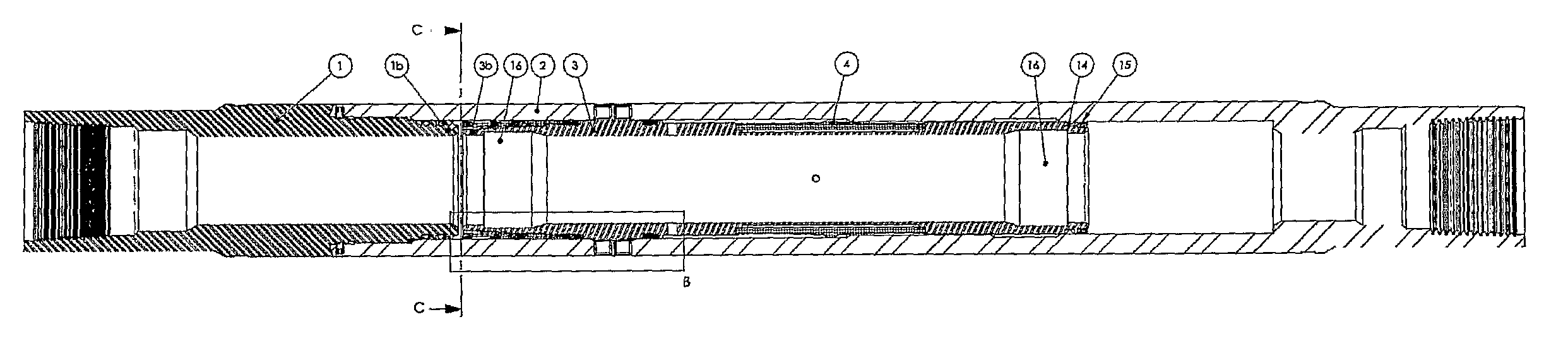
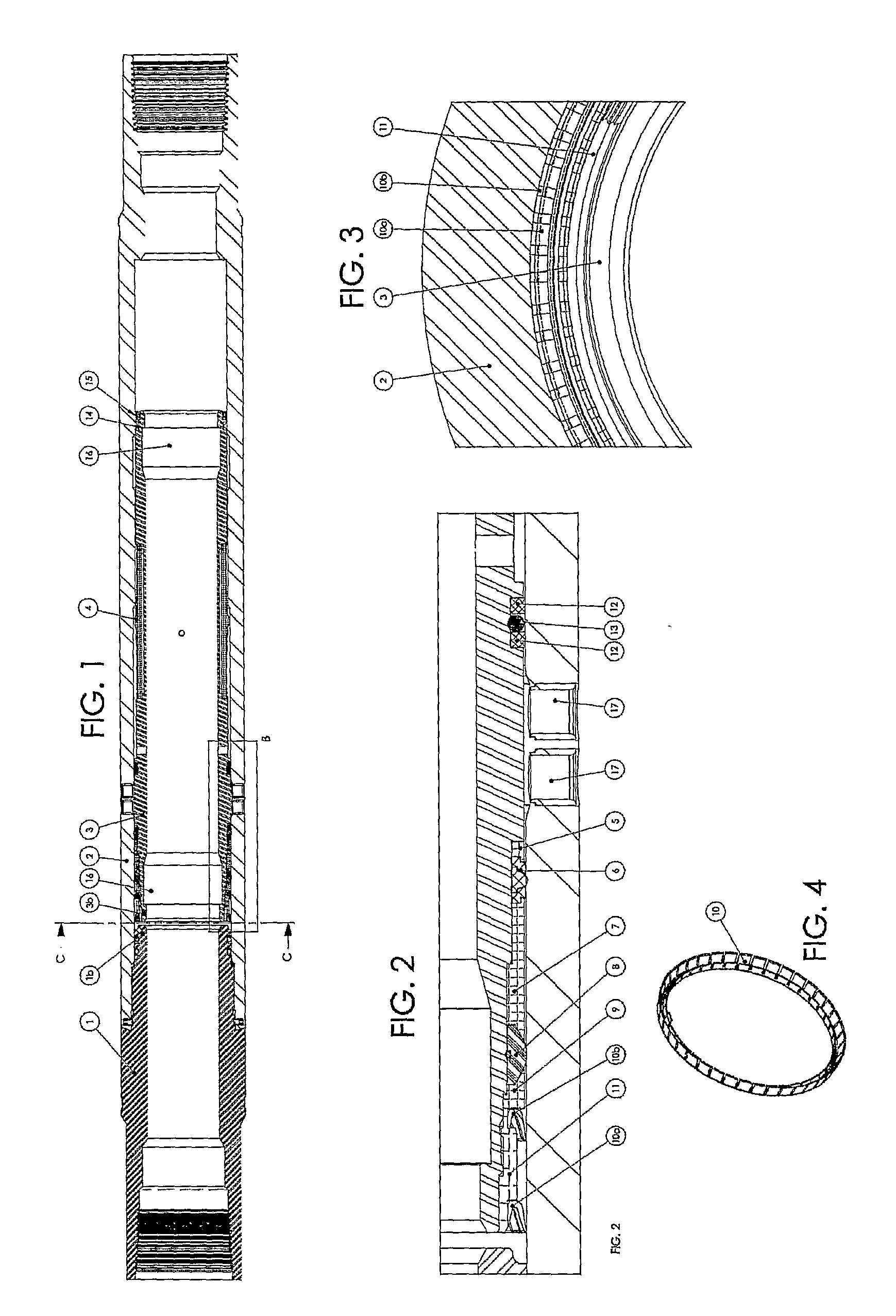
[0032]FIG. 1 is a longitudinal cross sectional view of a valve according to the invention. In FIG. 1, the valve is shown in a closed state. An end part 1 connected to a valve housing 2 form the outer shell of the valve. The valve housing 2 comprises radial side ports 17. An inner sliding sleeve 3 can be moved axially inside the valve housing 2 in order to open or close the radial side ports. As can be best seen in FIG. 2, the sliding sleeve 3 has no ports. Rather, the edge of the sleeve 3 is moved past the housing ports 17 to reach the open position. The inner sliding sleeve 3 is prevented from rotating in the valve housing 2 because it may become necessary to rotate an activating tool (not shown) if it should become stuck.

[0033]In FIG. 1, a flexible latch ring 4 connected to the sliding sleeve 3 abuts an inner shoulder along a circumference of the valve housing 2. In order to open the valve, the sliding sleeve 3 must be pulled towards the ring 4 (to the right in FIG. 1) with suffic...


PUM


Abstract

The present invention provides a robust, durable and reliable cylindrical valve having closable, radially extending openings for use in cementing, injection, including hydraulic fracturing, and production in wells having high pressures and large pressure differences. The valve may comprise scraping rings in order to remove deposits and the like when it is to be closed after use. Magnets or other suitable means indicates whether the valve is in an open or closed position.

Description

BACKGROUND[0001]1. Field of the Invention[0002]The present invention concerns a sliding sleeve valve for production, injection and cementing in wells in geological strata.[0003]2. Related and Prior Art[0004]Production of oil and gas, geothermal applications and drilling of wells for water involves drilling through rock, soil, or other geological formations. Oil / condensate, gas, water, geothermally heated water etc. is hereinafter referred to as production fluid, and can, e.g. in production of hydrocarbons and in geothermal applications, comprise several phases. The formations containing production fluids are usually divided into layers or strata. The drilling may occur vertically through one or more strata in order to reach the desired layer, and then possibly horizontally along one or more strata to provide as efficient wells as possible.[0005]Drilling in geological strata is done by rotating a drill bit at the end of a drill string and force it in the desired direction through geo...

Claims


Application Information

Patent Timeline
Patent Type & Authority Applications(United States)
IPC IPC(8): F16K5/00F16K37/00
CPCE21B34/14E21B2200/06
Inventor BRAEKKE, KRISTOFFER
Owner I TECH
Why Eureka
Try Eureka