System and method of moving target based calibration of non-uniformity compensation for optical imagers

Active Publication Date: 2011-03-01
RAYTHEON CO
View PDF15 Cites 9 Cited by
  • Summary
  • Abstract
  • Description
  • Claims
  • Application Information

AI Technical Summary

Benefits of technology

[0015]In another embodiment, the estimate of the test scene is spatially masked based on a priori knowledge of the test scene to create the estimated target images. The mask excludes areas of high spatial variability such as transitions between the target and background intensity levels and includes areas of low variability such as the interior of the target and an annular region in the background around the target. The mask effectively sets the weights in the excluded areas to zero and the weights in the included areas to one. Alternately, the mask can be used to explicitly set the weights in the excluded areas to zero and not be directly applied to the image data. For additional refinement, a gradient of the pixel values can be computed for the included areas. If individua

Problems solved by technology

These edge target images tend to be more difficult t

Method used


Image

  • System and method of moving target based calibration of non-uniformity compensation for optical imagers
  • System and method of moving target based calibration of non-uniformity compensation for optical imagers
  • System and method of moving target based calibration of non-uniformity compensation for optical imagers

Examples


Embodiment Construction

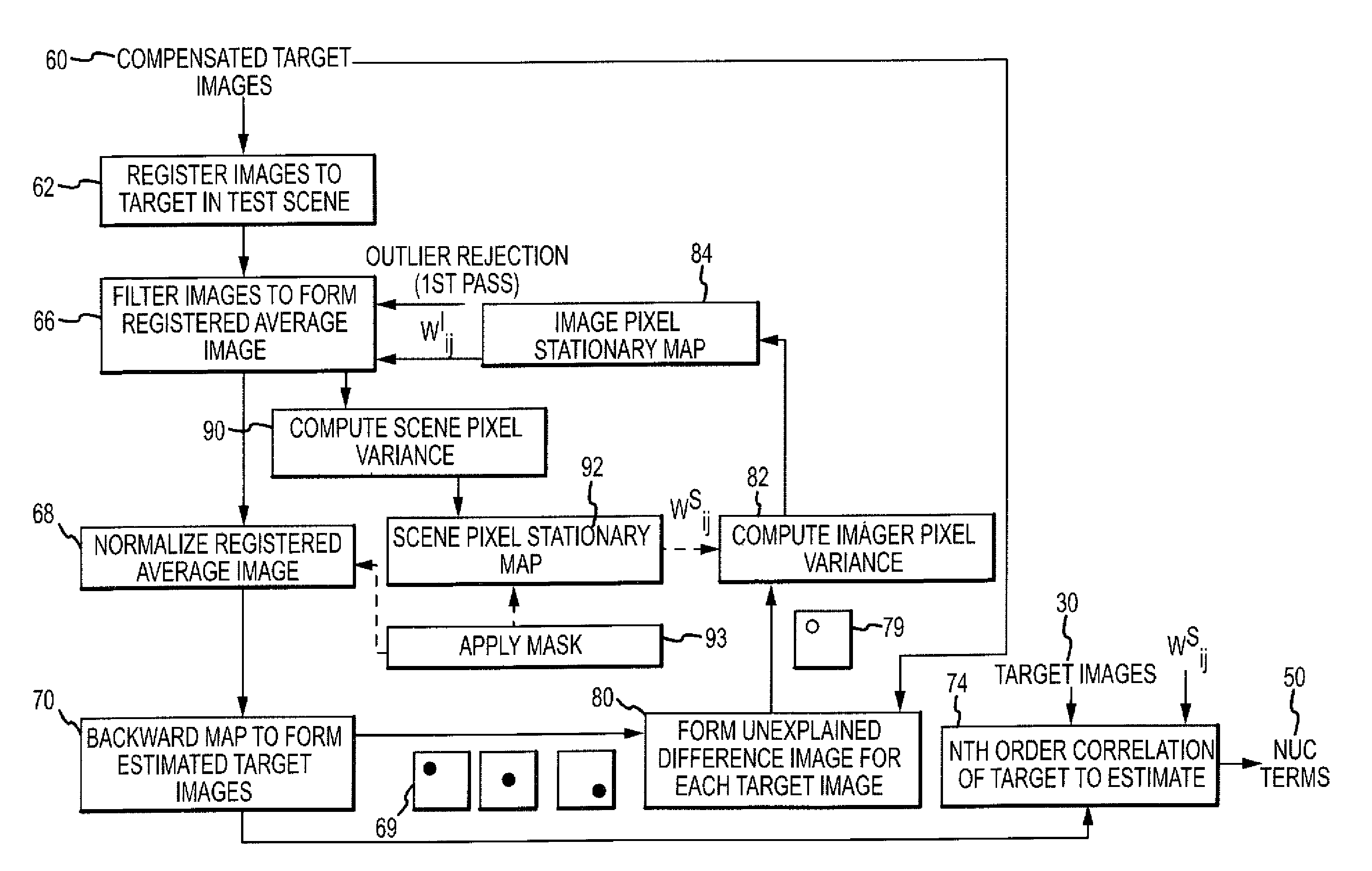
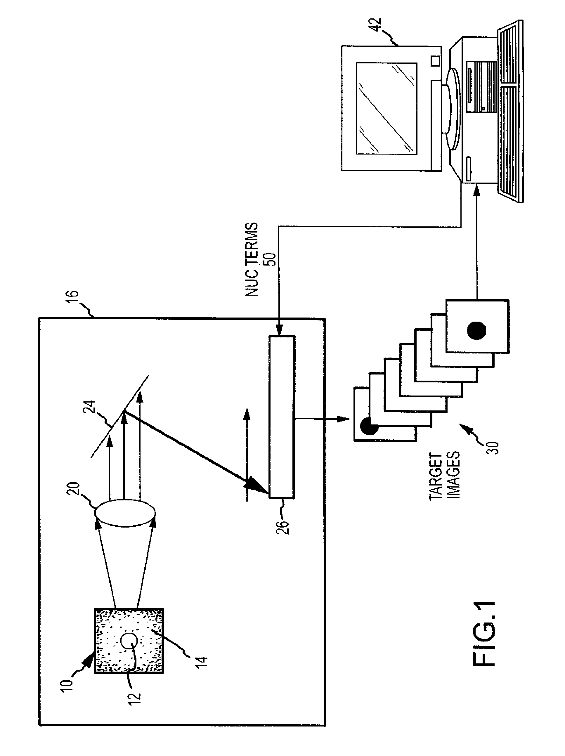
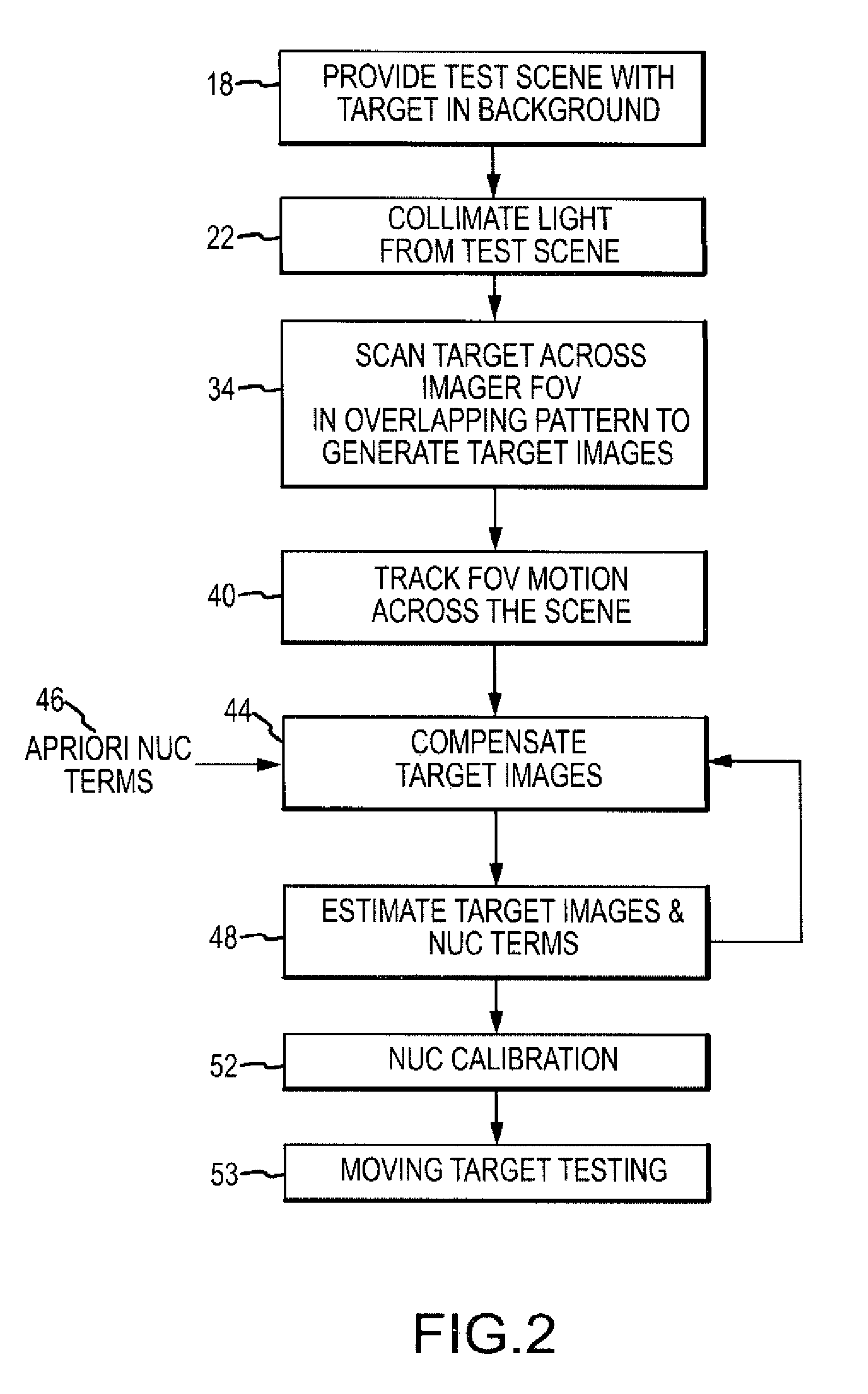
[0027]The present invention describes a system and method for precision calibration of non-uniformity compensation (NUC) terms including but not limited to the 1st order gain terms. The described approach allows for the use of the same test chamber to perform non-uniformity calibration and to perform the moving target tests. The current approach works by scanning a test scene having a target and a background at different illuminations in an overlapping pattern across the imager FOV and cross-referencing multiple intensity level measurements of each pixel of a test scene as viewed by different pixels in the imager; each imager pixel to be fully compensated (hereinafter referred to as a “fully-compensated imager pixel”) sees multiple different scene pixels and each scene pixel is seen by multiple fully compensated imager pixels. This approach is based on the simple yet novel premise that every pixel in the array that looks at the same thing should see the same thing. Depending upon th...


PUM


Abstract

A system and method for moving target based non-uniformity calibration for optical images. The described approach allows for the use of the same test chamber to perform non-uniformity calibration and moving target tests. The current approach works by scanning a test scene having a target and a background at different intensity levels in an overlapping pattern across the imager FOV and cross-referencing multiple measurements of each pixel of a test scene as viewed by different pixels in the imager; each fully-compensated image pixel sees multiple different scene pixels and each scene pixel is seen by multiple imager pixels. For each fully-compensated imager pixel, an Nth order correlation is performed on the measured and estimate pixel response data to calculate the NUC terms. This approach is based on the simple yet novel premise that every fully-compensated pixel in the array that looks at the same thing should see the same thing.

Description

CROSS-REFERENCE TO RELATED APPLICATIONS[0001]This application is a continuation-in-part of co-pending U.S. application Ser. No. 10 / 941,203 entitled “FLIR-to-Missile Boresight Correlation and Non-Uniformity Compensation of the Missile Seeker” and filed on Sep. 15, 2004 now U.S. Pat. No. 7,463,753 and claims priority under 35 U.S.C. 120.GOVERNMENTAL RIGHTS[0002]This invention was made with Government support under Contract HQ0006-01-C-0001 / 101616 awarded by the Ballistic Missile Defense Organization. The Government has certain rights in this invention.BACKGROUND OF THE INVENTION[0003]1. Field of the Invention[0004]This invention relates to the determination of non-uniformity compensation (NUC) terms for optical imagers, and more particularly to a low-cost method of calibrating precision NUC terms based on a moving target.[0005]2. Description of the Related Art[0006]Optoelectronic imagers such as Focal Plane Arrays (FPAs) in the IR, near visible, visible or other bands detect incident ...

Claims


Application Information

Patent Timeline
IPC IPC(8): G06K9/32H04N5/365H04N5/367
CPCH04N5/33H04N5/3655H04N5/3675H04N17/002F41G7/2253G01S3/7803G06T5/008G06T5/50G06T2200/32G06T2207/10016G06T2207/20216G06T2207/30208G06T2207/30212F41G7/002F41G7/2293H04N25/673H04N25/683
Inventor WILLIAMS, DARIN S.
Owner RAYTHEON CO
Why Eureka
Try Eureka