
Friction hinge for push-out style window

a technology of hinges and hinges, applied in the direction of door/window fittings, multi-purpose tools, construction, etc., to achieve the effect of facilitating cleaning or replacement and extending the window assembly

Active Publication Date: 2011-03-08
TRUTH HARDWARE
View PDF13 Cites 17 Cited by
  • Summary
  • Abstract
  • Description
  • Claims
  • Application Information

AI Technical Summary

Benefits of technology

[0010]The friction slider assembly can include a slider, a collar, and a friction adjustment member. The friction adjustment member generally includes a suitable adjusting mechanism such as, for example, a set screw or cam arrangement for variably adjusting the frictional engagement of the slider and the friction arm. The friction adjustment member can operate against the slider in either a vertical or horizontal axis. With the friction arm, additional frictional resistance is provided so as to retain a push-out style window in a desired position when exposed to external forces such as, for example, wind. In addition, the friction adjustment member enables the frictional resistance provided by the friction hinge assembly to be manually adjusted by a user.
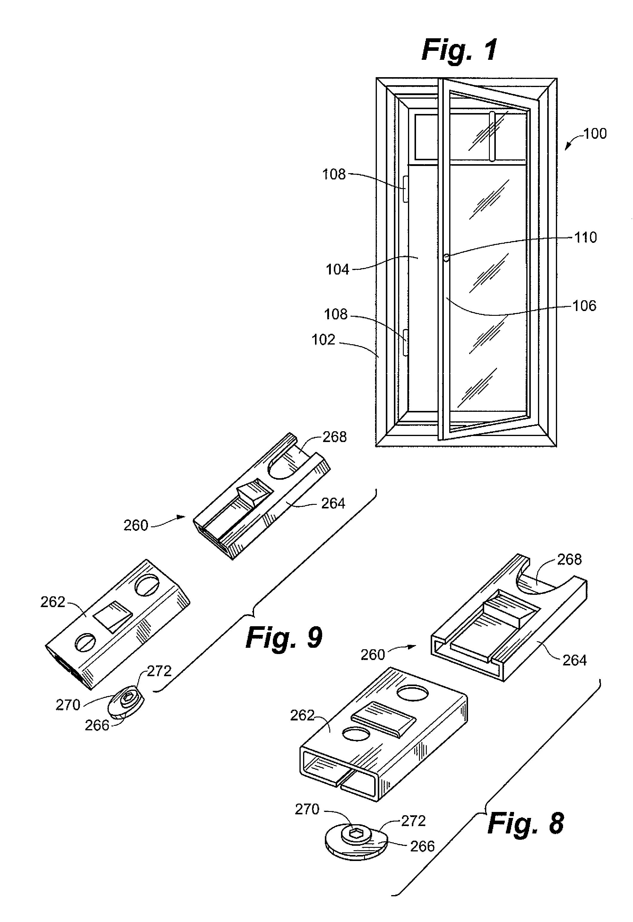
[0014]In yet another aspect, a slider assembly can include a friction slider having an opening, seam, or other mechanical or non-mechanical mechanism enabling selective detaching of the slider assembly from a support arm. Such an assembly may enable ease of cleaning or replacement of components of a slider assembly, including a friction slider as part of a slider assembly.
[0015]In a further aspect, a friction slider assembly can include an offset formed on a friction slider or sleeve, which can provide creep relief for a friction slider or sleeve when the hinge is closed, which is the state in which hinge is in for a majority of the life cycle of the window. The offset can correspond to an angled offset included on support arm enabling the opening and closing of the hinge. The inclusion of the offset on the sleeve can enable the life of friction slider assembly and thus the window assembly to be lengthened.

Problems solved by technology

While push-out style windows have provided an easy and elegant window system, they can suffer problems related to maintaining the desired open position under loading conditions such as, for example, on a windy day.

Method used


Image

  • Friction hinge for push-out style window
  • Friction hinge for push-out style window
  • Friction hinge for push-out style window

Examples


Embodiment Construction

[0043]A push-out style window assembly 100 is shown generally in FIG. 1. Push style window assembly 100 generally includes a window frame 102, a sash 104, and an inwardly rotatable screen 106. Window frame 102 generally includes one or more latching members 108 for operably locking the sash 104 in a closed disposition. Inwardly rotatable screen 106 generally includes a handle 110 enabling a user to pull the inwardly rotatable screen 106 into a structure when it is desired to open the sash 104. As depicted in FIG. 1, push-out style window assembly 100 is a casement window, though the friction hinge assembly of embodiments of the present invention can be utilized with a variety of push-out style window designs, for example awning style windows.

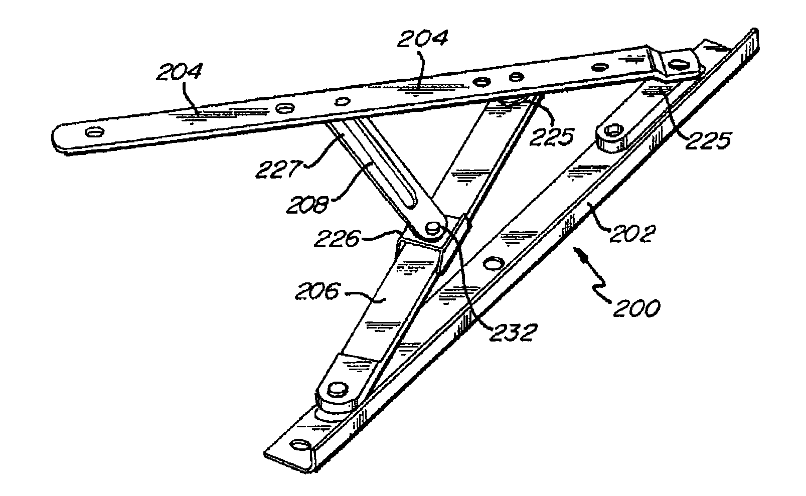
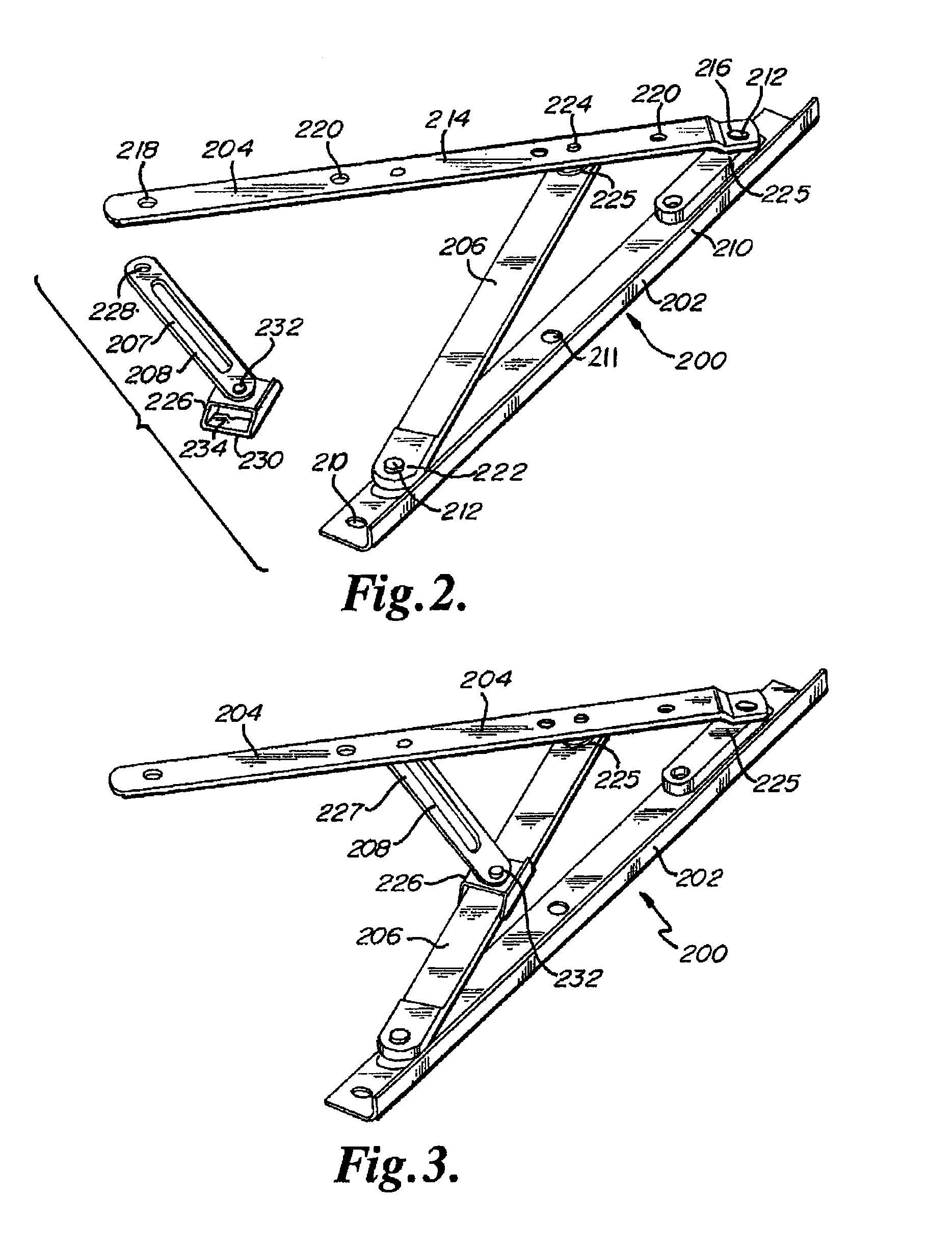
[0044]Referring to FIGS. 2, 3 and 4, an embodiment of a friction hinge assembly 200 generally includes a track 202, a sash arm 204, a support arm 206, and a slidable friction arm assembly 208. Track 202 generally includes a track body 210, a plu...


PUM


Abstract

A push-out style window assembly including window hardware for frictionally retaining an open position of the window under typical loading conditions. A push-out style window assembly generally includes a friction hinge assembly including a track, a sash arm, a support arm, and a friction arm. The friction arm can include an adjustable and / or detachable slide enabling adjustment of a frictional resistance between the friction slider and the support arm. Using the friction arm, frictional resistance is provided so as to provide control both during opening of the window and in retaining the position of an open window.

Description

RELATED APPLICATIONS[0001]This application claims the benefit of U.S. Provisional Patent Application Nos. 60 / 876,069, filed Dec. 20, 2006, and 60 / 988,871 filed Nov. 9, 2007, both of which are hereby incorporated herein by reference.FIELD OF THE INVENTION[0002]The present invention relates generally to push-out style windows. More particularly, embodiments of the present invention relate to hinges for frictionally securing a push-out style window in an open position.BACKGROUND OF THE INVENTION[0003]Push-out style windows have been installed with increasing frequency due in part to their style and increased viewability therethrough. These windows are available in, for example, casement and awning types. Generally, push-out style windows include an outer window and a hingedly mounted screen that is inwardly rotatable. By rotating the hinged screen inwardly, access is provided to the outer window from the inside. The outer window is generally also hingedly mounted so as to be outwardly ...

Claims


Application Information

Patent Timeline
Patent Type & Authority Patents(United States)
IPC IPC(8): E05D15/00
CPCE05D15/30E05Y2201/21E05Y2201/25E05Y2201/26E05Y2201/264Y10T16/545Y10T16/5474Y10T16/5476Y10T16/5475Y10T16/5327E05Y2900/148
Inventor DORING, CRAIG M.SOUKUP, THOMASSEASER, JAMES
Owner TRUTH HARDWARE
Learn More