
Vehicle

a technology of electric motor and vehicle, which is applied in the field of vehicles, can solve the problems of loss of vehicle weight balance and inability to adjust the capacity of the battery in response to a user's request, and achieve the effect of vehicle weight balan

Inactive Publication Date: 2011-03-08
TOYOTA JIDOSHA KK
View PDF72 Cites 20 Cited by
  • Summary
  • Abstract
  • Description
  • Claims
  • Application Information

AI Technical Summary

Benefits of technology

The invention provides a vehicle that can change its battery capacity based on the user's needs, while ensuring that the vehicle remains balanced when the battery capacity is changed. This is achieved by a design that includes a fixed center of gravity, a detachable first battery, and a detachable second battery. The vehicle can also have a detecting unit to detect which battery is attached or detached, and a control unit to switch between the two batteries. The second battery can be placed in either the driver's seat or the front passenger seat, or both. The vehicle can also have a floor panel and a shock absorbing member to hold the second battery in place. Overall, the invention allows for flexible battery capacity while maintaining the vehicle's balance.

Problems solved by technology

Therefore, there is a problem that, for example, if a portion of the battery modules at an end is detached, the weight balance of the vehicle is lost.
In the high-voltage electrical component casing arrangement structure described in JP-A-2005-1655, the battery is not detachable and, therefore, the capacity of the battery is not adjustable in response to a user's request.

Method used


Image

  • Vehicle
  • Vehicle
  • Vehicle

Examples


first embodiment

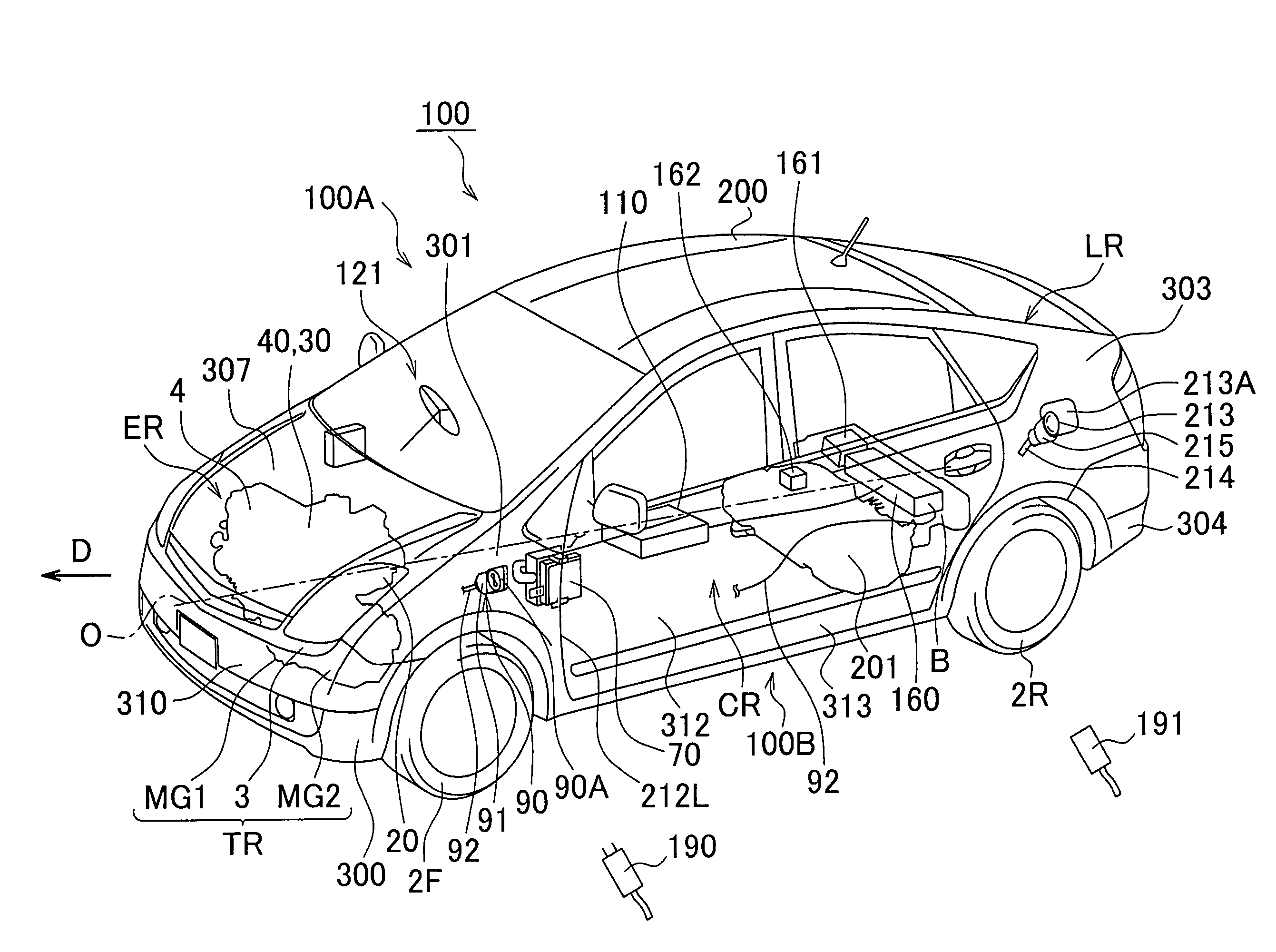
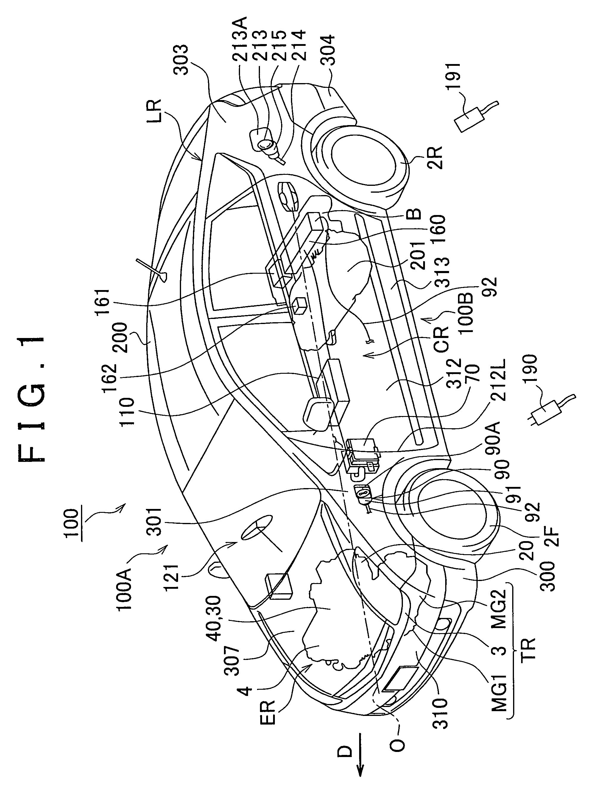
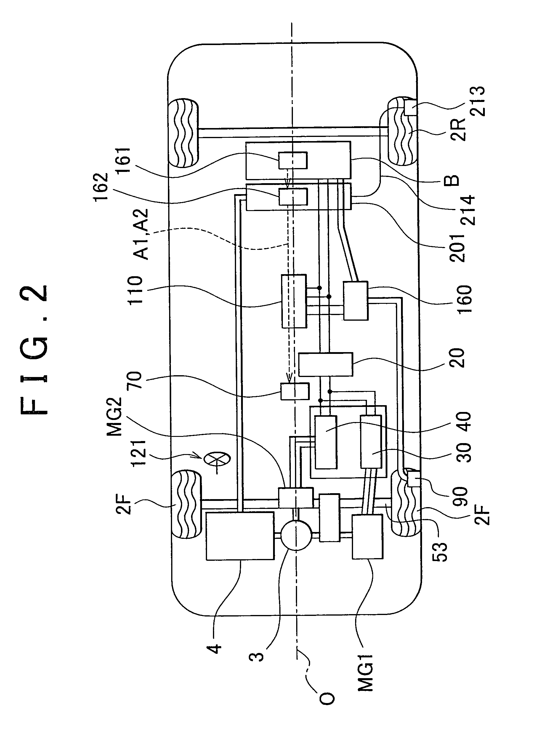
[0037]A hybrid vehicle 100 according to a first embodiment of the invention will be described with reference to FIG. 1 to FIG. 10. FIG. 1 is a perspective view that shows the schematic configuration of the hybrid vehicle 100 according to the first embodiment of the invention. FIG. 2 is a block diagram that shows the schematic configuration of FIG. 1.

[0038]As shown in FIG. 1, the hybrid vehicle 100 includes a vehicle body 200, a pair of front wheels 2F and a pair of rear wheels 2R. The vehicle body 200 is formed of a body and exterior components. The pair of front wheels 2F are provided at the front in a traveling direction D of the hybrid vehicle 100. The pair of rear wheels 2R are provided at the rear in the traveling direction D. The hybrid vehicle 100 further includes a transaxle TR, an engine 4 and an ECU 70. The ECU 70 controls the transaxle TR and the engine 4 for driving.

[0039]The vehicle body 200 includes an engine compartment (driving portion compartment) ER, a passenger co...

second embodiment

[0100]A hybrid vehicle 100 according to a second embodiment of the invention will be described with reference to FIG. 11 to FIG. 13.

[0101]Note that in the configuration shown in FIG. 11 to FIG. 13, like reference numerals denote like or equivalent components to those shown in FIG. 1 to FIG. 10, and the description thereof may be omitted where appropriate.

[0102]FIG. 11 is a block diagram of the hybrid vehicle 100 according to the second embodiment of the invention. As shown in FIG. 11, the detachable battery 110 is electrically connected in series with the battery B.

[0103]Here, the detachable battery 110 is equipped with a connector 173 and a connector 174. A connector 171 connected to the battery B is fitted to the connector 173. A connector 172 connected to the step-up converter 20 is fitted to the connector 174.

[0104]In this way, when the detachable battery 110 connected in series with the battery B is made detachable, it is possible to increase a voltage supplied to the step-up c...


PUM


Abstract

A vehicle includes: rotatable wheels; a rotary electric machine that generates power for driving the wheels; a battery that supplies electric power to the rotary electric machine and that is fixed to the vehicle; and a detachable battery that supplies electric power to the rotary electric machine, that is detachable from the vehicle and that is arranged at a center in a width direction of the vehicle.

Description

INCORPORATION BY REFERENCE[0001]The disclosure of Japanese Patent Application No. 2008-162053 filed on Jun. 20, 2008 including the specification, drawings and abstract is incorporated herein by reference in its entirety.BACKGROUND OF THE INVENTION[0002]1. Field of the Invention[0003]The invention relates to a vehicle and, more particularly, to a vehicle equipped with an electrical storage device and a drive rotary electric machine.[0004]2. Description of the Related Art[0005]Various vehicles-equipped with an electrical storage device and a drive rotary electric machine have been suggested. For example, Japanese Patent Application Publication No. 2004-262357 (JP-A-2004-262357) describes an electric vehicle that is equipped with a changeable portion, battery modules, and a fixed battery. The changeable portion is provided at the rearmost space of the electric vehicle. The battery modules are accommodated in the changeable portion. The fixed battery is fixed to a floor, or the like. Th...

Claims


Application Information

Patent Timeline
Patent Type & Authority Patents(United States)
IPC IPC(8): B60W10/24B60R16/04B60L50/16
CPCB60K1/04B60K6/365B60K6/445B60K6/547B60L11/1877B60K2001/0427B60K2001/0433B60K2001/0455B60K2001/0472Y02T10/6239Y02T10/6269Y02T10/7005Y02T10/705B60L50/66Y02T10/62Y02T10/70
Inventor SUZUKI, NAOTOICHIKAWA, SHINJIANG, WANLENGMURASATO, KENJI
Owner TOYOTA JIDOSHA KK
Learn More