Blind fastener and method

a blind rivet and fastener technology, applied in the field of blind rivet elements, can solve the problems of unweakened hank wall and available entire wall thickness, and achieve the effect of increasing the length/width ratio

Active Publication Date: 2011-03-08
DREGISCHAN SIMONE +1
View PDF20 Cites 10 Cited by
  • Summary
  • Abstract
  • Description
  • Claims
  • Application Information

AI Technical Summary

Benefits of technology

Since the present blind rivet does not have long slots with webs located between them, the blind rivet nut can have a substantially shorter build or profile, and has a different configuration of the bead. The bead takes the form of a very large, essentially continuous bearing surface, in contrast to large sector regions in which a blind rivet element having slots running along its longitudinal extent does not bear with their closing head against the metal sheet. There is therefore also no risk that the blind rivet element connected to the metal sheet will rotate in relation to the latter during subsequent screwing. The clamping force of the riveted blind rivet element is therefore substantially higher.
Since no long slots are required extending essentially over the length of the deformation portion in the longitudinal direction of the deformation portion, the blind rivet element can have a very short build or profile, along with a substantially larger clamping range. Owing to the fact that, during setting, the bending of the blind rivet element starts in a specific region of the blind rivet element, and, consequently, a bulging bend can be determined in a clearly defined manner during the setting of blind rivet element as a function of the thickness of the metal sheet, and the blind rivet element can be set accurately. The outer distance of the closing head, in this case formed, from the longitudinal axis of the shank is substantially shorter than in the variant, known from the prior art, with the long slots running along the longitudinal extent of the shank.
The blind rivet element can be produced particularly simply and cost-effectively if the shank has a constant inside and / or outside diameter between the setting head and the internal thread of the shank. Ideally, therefore, the shank has neither an outer nor an inner jump in diameter in this region.

Problems solved by technology

In the other regions, the shank wall remains unweakened, with the result that the entire wall thickness is available there.

Method used


Image

  • Blind fastener and method
  • Blind fastener and method
  • Blind fastener and method

Examples


first embodiment

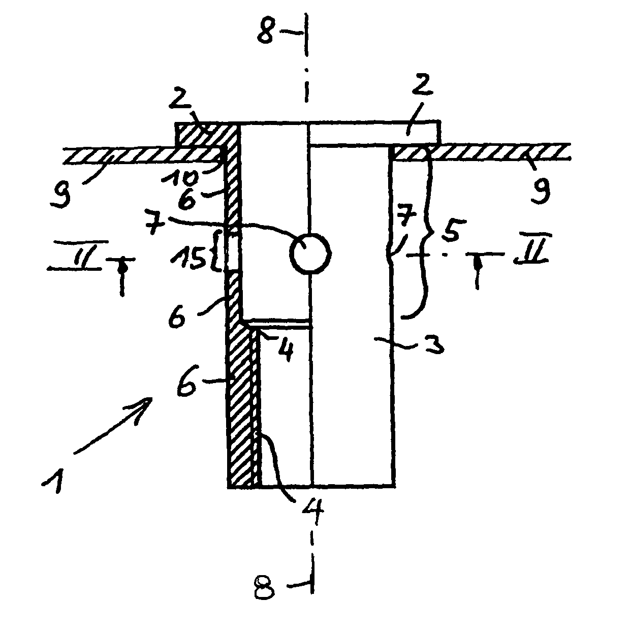
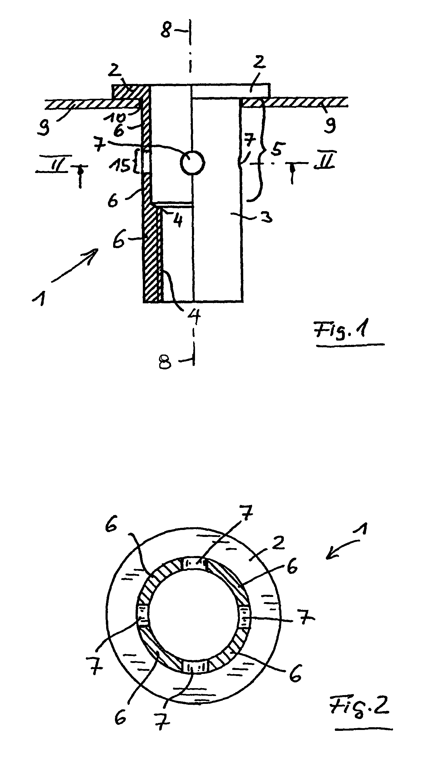
FIGS. 1 and 2 illustrate, for the invention, the blind rivet nut 1 before it is set. The blind rivet nut 1 has a setting head 2 and a shank 3. The shank 3 is provided with an internal thread 4 in the region of its distal end or the end facing away from the setting head 2. A deformation portion 5 is positioned between the internal thread 4 and the setting head 2. Basically, the deformation portion 5 extends as far as the setting head 2, since the blind rivet nut 1 could be deformed in this region when a pull is introduced into the internal thread 4. In practice, since the blind rivet nut is to be connected to a plate-shaped component 9, such as metal sheet 9, this deformation portion 5 extends only as far as that side of the metal sheet which faces away from the setting head 2.

The shank 3 has, over the circumference of the shank 3, a weakening of shank wall 6 in a central region of the deformation portion 5. In the embodiment shown in FIGS. 1 and 2, this weakening is formed by four h...

third embodiment

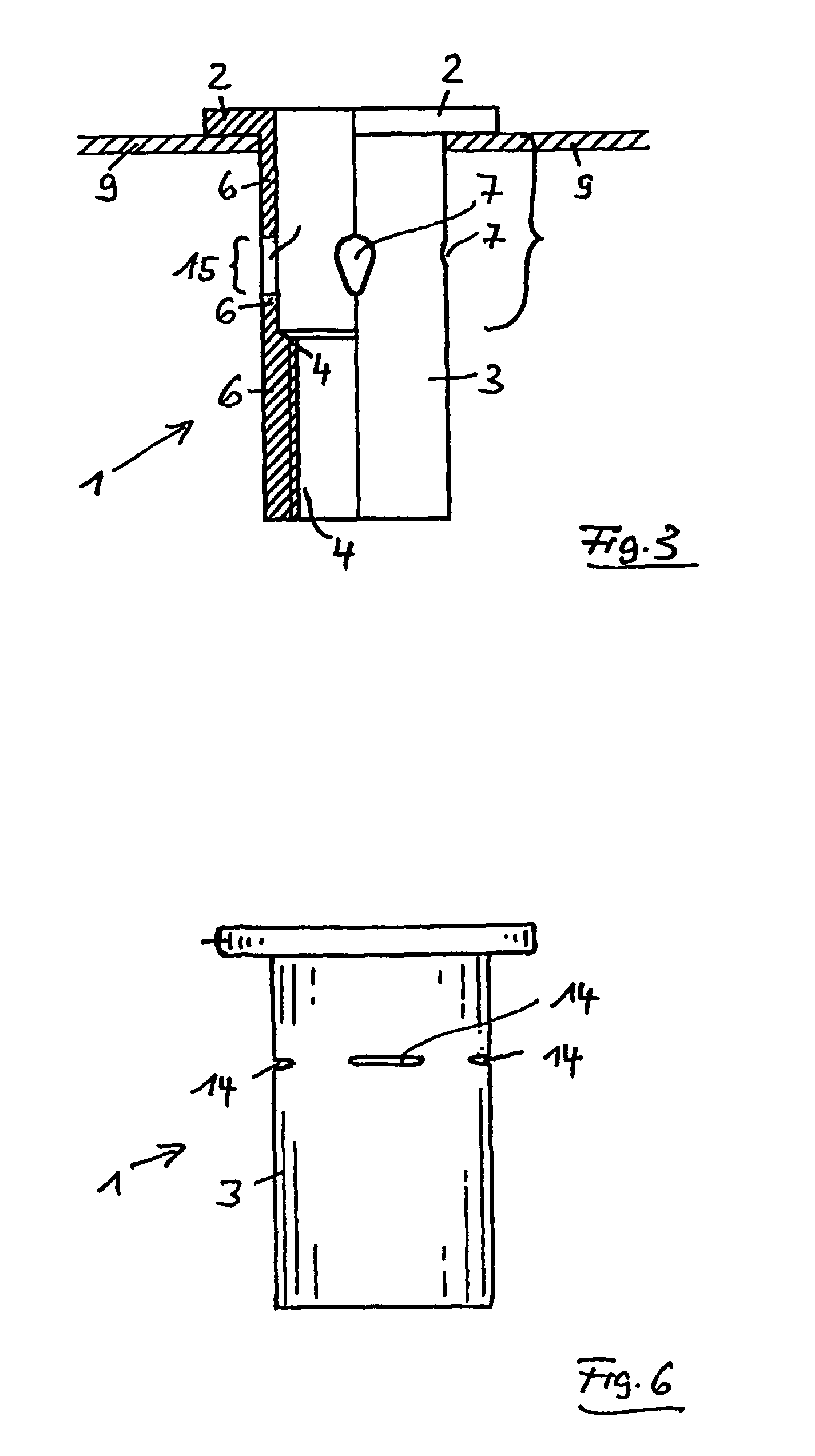
FIG. 6 shows the blind rivet nut 1. It differs from the other two embodiments only in that, in relation to the initial state illustrated for these, instead of the configuration with the four holes 7 of circular or drop-shaped cross section, an arrangement with four slots 14 at a corresponding location is provided. Before the deformation of the deformation portion 5, these four slots14 are therefore already present and, during the setting of the blind rivet nut, are further deformed tangentially, starting from this shape, with the result that the slots 14 are lengthened.

The blind rivet nut 1 according to the embodiment shown in FIG. 7 is modified, as compared with that according to FIGS. 1 and 2, only to the effect that, instead of the holes 7 of circular cross section, holes 7 are provided which are designed as long holes, the longitudinal axis of the long holes running parallel to the longitudinal axis 8 of the shank 3.

The embodiment according to FIG. 8 differs from that according ...


PUM

PropertyMeasurementUnit
sizesaaaaaaaaaa
sizesaaaaaaaaaa
sizesaaaaaaaaaa

Abstract

A blind fastener has a setting head portion and a shank portion having one end connected with the setting head portion and an opposite end with an internal thread or a threaded bolt receptacle. The shank has a sidewall with an outside diameter smaller than the diameter of the setting head portion, and is configured for close reception in an aperture of the workpiece prior to being upset. The sidewall has a deformation area that is disposed between the setting head portion and the internal thread or the threaded bolt receptacle, and is upset radially outwardly to secure the fastener to the workpiece. The deformation area includes a central circumferential region which provides sole weakening for the sidewall.

Description

CLAIM OF PRIORITYApplicant hereby claims the priority benefits under the provisions of 35 U.S.C. §119, basing said claim of priority on European Patent Application Serial No. 06 022 882.2, filed Nov. 3, 2006 and European Patent Application Serial No. 06 024 927.3, filed Dec. 1, 2006. In accordance with the provisions of 35 U.S.C. §119 and Rule 55(b), certified copies of the above-listed European patent applications will be filed before grant of a patent.BACKGROUND OF THE INVENTIONThe present invention relates to fasteners, and in particular to a blind rivet element with a setting head and a shank. The shank has an internal thread or a receptacle for a threaded bolt at its distal end, and a deformation area between the internal thread or the bolt receptacle. The setting head has a larger outside diameter than the shank. The invention relates, furthermore, to a novel use of a blind rivet element.Blind rivet elements of this type are designed, for example, as a blind rivet nut or a bli...

Claims


Application Information

Patent Timeline
Patent Type & Authority Patents(United States)
IPC IPC(8): F16B13/06
CPCF16B37/067Y10T29/5303
Inventor SCHRUFF, HERBERT
Owner DREGISCHAN SIMONE
Why Eureka
Try Eureka