Catheter having staggered lumens and method

a catheter and lumen technology, applied in the field of multiple lumen catheters, can solve the problems of high pressure, inability to meet the demands of high pressure applications, and often very ill insertion of piccs, and achieve the effect of increasing the resistance of the catheter to cross lumen leakag

Active Publication Date: 2011-03-08
BECTON DICKINSON & CO
View PDF42 Cites 6 Cited by
  • Summary
  • Abstract
  • Description
  • Claims
  • Application Information

AI Technical Summary

Benefits of technology

[0013]The apparatus of the present invention has been developed in response to the present state of the art, and in particular, in response to the problems and needs in the art that have not yet been fully solved by currently available catheters and more specifically PICCs. Thus, the present invention provides a multiple lumen catheter for use in the high pressure administration of liquids that increases the catheters resistance to cross lumen leakage at the hub.
[0015]The first lumen and the second lumen each have an opening that is axially spaced from the other. Thus, when the lumens of the multiple lumen catheter tube are aligned along the longitudinal axis, the opening of the first lumen is axially spaced from the opening of the second lumen. In other words, the openings of the lumens are staggered along the longitudinal axis. By spacing the openings of the first lumen and the second lumen, the radial stresses induced into the catheter tubing during the attachment of the hub are reduced. In some configurations, the hub of the catheter may be attached to the catheter tube so that the opening of the first lumen and the opening of the second lumen are disposed within the hub. In some configurations, an end of the catheter tube may be disposed within the hub.
[0021]The method may also include the steps of removing the first mandrel from the first lumen and removing the second mandrel from the second lumen. The first mandrel may include a raised contact surface so that when the first mandrel is inserted into the opening of the first lumen, the raised contact surface abuts the inner wall of the catheter tube. The raised contact surface acts as a stop to prevent melted plastic during an injection molding process from cooling into a thin plastic flap between the inner wall and the mandrel. If a flap is formed, it may interfere with the use of the catheter and block the flow of fluid through the first lumen. Additionally, the bend in the catheter tube may be positioned proximate the raised contact surface during the injection molding process. The first mandrel may also include a bend which may be positioned proximate the raised contact surface.

Problems solved by technology

Thus, the pressures involved in CT procedures are much higher.
The majority of currently available PICCs are only able to safely function at pressures less than 100 pounds per square inch (psi) and thus, are unable to meet the demands of high pressure applications where the pressures may reach and exceed 300 psi.
However, patients having an inserted PICC are often very ill and gaining access to a vein in another location may be difficult.
More specifically, as veins are accessed over time, veins may become inaccessible through damage and scar tissue.
When these currently available high pressure PICCs are used at high pressure, however the PICCs may develop cross-lumen leakage.
This can be a serious problem because some medications that are simultaneously administered to a patient through a multiple lumen catheter may form a precipitate if mixed.
The precipitate may partially or completely block the PICC, resulting in an unknown quantity of medication being administered to the patient.
Alternatively, some medications if mixed prior to being dispersed through the blood stream may be extremely toxic and harmful to the patient.
Additionally, high pressure PICCs are expensive to manufacture.
The metal hub must be machined to relatively tight tolerances and the metal itself may react to the medications being administered, which may limit its usefulness.
Additionally, the metal hub complicates disposal of the catheter because it may need to be disposed of separately from the plastic portion of the catheter.
Another short coming of the prior art is that the catheter may still develop cross-lumen leakage at the interface between the metal hub and the catheter tubing.
In addition, low pressure PICCs made entirely of plastic may suffer from cross-lumen leakage at pressures as low as 40 psi.
This stress and stretch of the inner wall of the multiple lumen catheter tube can result of cross-lumen leakage even under relatively low pressures, such as 40 psi.
Often these fingers of plastic have cooled enough that they fail to fully adhere to the multiple lumen catheter tube.
Thus, these fingers of plastic may act as flaps that may potentially reduce the flow of liquids through that lumen of the catheter or may become dislodged and potentially flow into a patient.

Method used


Image

  • Catheter having staggered lumens and method
  • Catheter having staggered lumens and method
  • Catheter having staggered lumens and method

Examples


Embodiment Construction

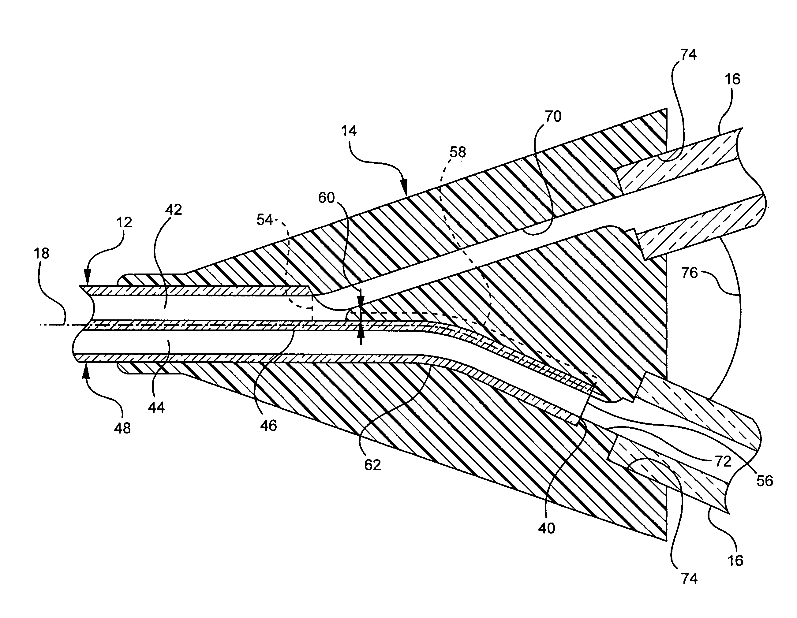
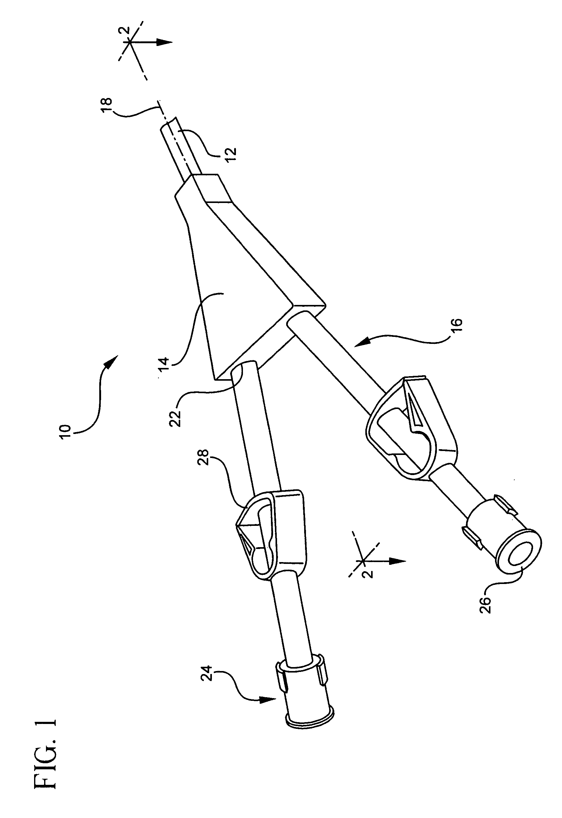
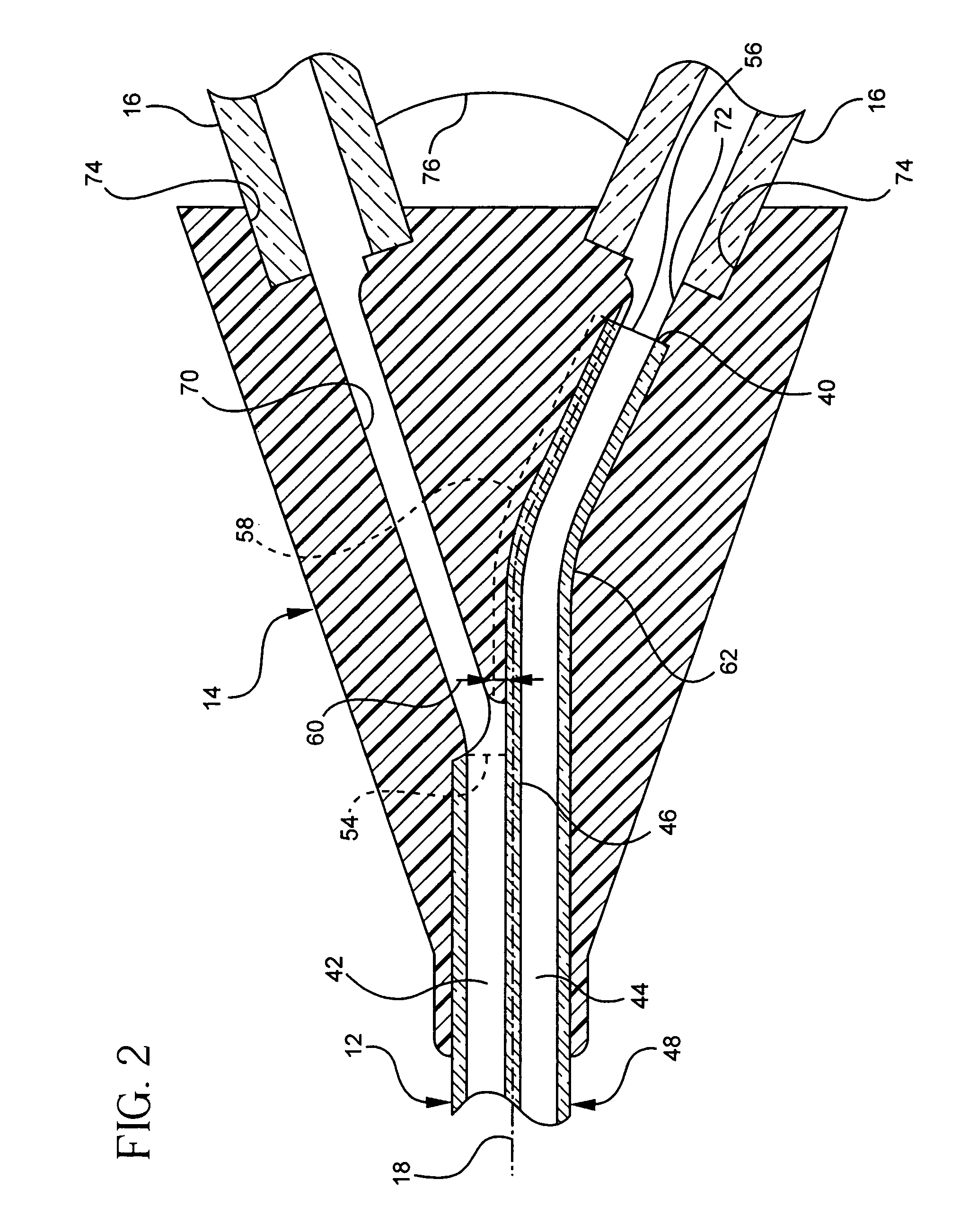
[0033]The presently preferred embodiments of the present invention will be best understood by reference to the drawings, wherein like parts are designated by like numerals throughout. It will be readily understood that the components of the present invention, as generally described and illustrated in the figures herein, could be arranged and designed in a wide variety of different configurations. Thus, the following more detailed description of the embodiments of the catheter of the present invention, as represented in FIGS. 1 through 6, is not intended to limit the scope of the invention, as claimed, but is merely representative of presently preferred embodiments of the invention.

[0034]In accordance with the invention as embodied and broadly described herein in the preferred embodiment, a type of catheter is provided. More specifically, the catheter shown is a PICC 10. According to one embodiment, the PICC 10 may include a multiple lumen catheter tube 12, a hub 14, and extension le...


PUM


Abstract

A catheter may include a multiple lumen catheter tube, a hub attached to the catheter tube, and a first extension leg and a second extension leg attached to the hub. The multiple lumen catheter tube may include a longitudinal axis, an end, a first lumen, and a second lumen. The first lumen and the second lumen extend through the catheter tube along the longitudinal axis and each having an opening. The end of the catheter tube and the openings of the lumen may be disposed within the hub so that the opening of the first lumen is axially spaced with the end of the catheter tube. The first extension leg may be coupled to the first lumen and the second extension leg may be coupled to the second lumen for the separate delivery of fluids to the lumens.

Description

BACKGROUND OF THE INVENTION[0001]The present invention relates to venous access catheters. More specifically, the present invention relates to a multiple lumen catheter for improved resistance to cross lumen leakage at the hub and a method for making a catheter that provides improved resistance to cross lumen leakage at the hub. For example, a multiple lumen catheter according to the invention may be a peripherally inserted central catheter (PICC) or any other type of multiple lumen catheter known in the art.[0002]A PICC is one type of catheter that may be used for the high pressure delivery of intravenous fluids. Previously, PICCs have been used for the low pressure delivery of intravenous fluids and medications. More recently it has become desirable to use a PICC for the administration of contrast agents during diagnostic Computer Tomography (CT) procedures and other radiographic procedures.[0003]A PICC is a catheter that may be inserted in a peripheral location, such as the arm o...

Claims


Application Information

Patent Timeline
Patent Type & Authority Patents(United States)
IPC IPC(8): A61M25/00A61M31/00
CPCA61M25/0009A61M25/0028A61M2025/0098A61M2025/0031A61M2025/0037A61M25/0097
Inventor BORDEN, JONATHAN R.TODD, DANIEL H.
Owner BECTON DICKINSON & CO
Why Eureka
Try Eureka