Technique for dynamically splitting MPLS TE-LSPs

a dynamic splitting and label switching technology, applied in the field of computer networks, can solve the problems that the te-lsp may need to be split into smaller lsps, and achieve the effects of optimal load balance, short paths, and increased bandwidth reserv

Active Publication Date: 2011-03-08
CISCO TECH INC
View PDF33 Cites 17 Cited by
  • Summary
  • Abstract
  • Description
  • Claims
  • Application Information

AI Technical Summary

Benefits of technology

[0023]Advantageously, the novel technique dynamically splits TE-LSPs in a computer network. By splitting larger TE-LSPs, the novel technique increases the ability to reserve larger amounts of bandwidth for traffic flows using smaller related TE-LSPs, e.g., without having to sacrifice performance that may generally be associated with placing larger TE-LSPs. For instance, by splitting TE-LSPs, shorter paths may become available for smaller related TE-LSPs than for a single larger TE-LSP, thus allowing more traffic to follow the shorter paths. Also, the novel technique allows for traffic originally meant to traverse larger TE-LSPs to be more optimally load balanced across the network through a plurality of smaller TE-LSPs. Further, the dynamic nature of the novel technique alleviates the need for cumbersome manual configuration.

Problems solved by technology

For instance, if no alternative paths exist that could support the larger TE-LSP except for those with an unacceptable metric increase (e.g., cost, delay, hop-count, etc.), then the larger TE-LSP may need to be split.

Method used


Image

  • Technique for dynamically splitting MPLS TE-LSPs
  • Technique for dynamically splitting MPLS TE-LSPs
  • Technique for dynamically splitting MPLS TE-LSPs

Examples


Embodiment Construction

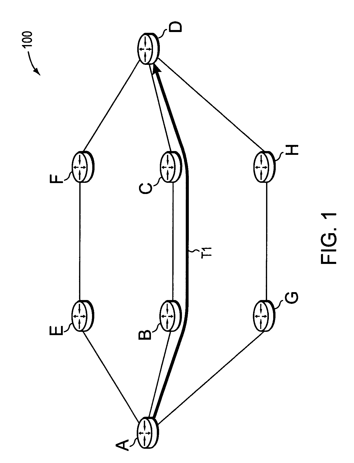
[0033]FIG. 1 is a schematic block diagram of an exemplary computer network 100 comprising routers A-H (e.g., intra-domain routers) interconnected through links as shown. The links between the routers may have an associated metric value (e.g., cost), and available bandwidth value, as described below. Network 100 may be contained within a single autonomous system (AS) or area, or may span multiple areas under certain circumstances as will be understood by those skilled in the art. An AS is herein defined to be a group of intermediate nodes, such as inter-domain and / or intradomain routers, within a network that are subject to a common authority and execute one or more inter-domain and / or intradomain routing protocols. Although the network 100 is illustratively shown within a single AS, those skilled in the art will appreciate that the network may alternatively be configured as routing domains or other networks or subnetworks. Notably, any number of nodes or routers may be used in the n...


PUM


Abstract

A technique dynamically splits Traffic Engineering (TE) Label Switched Paths (LSPs) in a computer network. According to the novel technique, a head-end node may determine that a TE-LSP to a destination needs to be sized to a larger bandwidth (a “larger” TE-LSP) than currently available over a single path to the destination (e.g., a path that may also be required to meet other constraints, such as cost, delay, etc.). In response, the head-end node may dynamically “split” the larger TE-LSP, and create a first split TE-LSP over a best (e.g., shortest) available path (e.g., that meets other constraints). The first split TE-LSP may reserve a maximum available bandwidth for that best available path. The head-end node may then continue recursively creating subsequent split TE-LSPs for any remaining bandwidth of the larger TE-LSP over available paths until the larger TE-LSP may no longer be split (e.g., all bandwidth has been placed, configurable maximum number of splits reached, etc.). Notably, the split TE-LSPs may be “re-groomed” at a later time to recombine and reorganize the split TE-LSPs.

Description

BACKGROUND OF THE INVENTION[0001]1. Field of the Invention[0002]The present invention relates to computer networks and more particularly to dynamically splitting Traffic Engineering (TE) Label Switched Paths (LSPs) in a computer network.[0003]2. Background Information[0004]A computer network is a geographically distributed collection of nodes interconnected by communication links and segments for transporting data between end nodes, such as personal computers and workstations. Many types of networks are available, with the types ranging from local area networks (LANs) to wide area networks (WANs). LANs typically connect the nodes over dedicated private communications links located in the same general physical location, such as a building or campus. WANs, on the other hand, typically connect geographically dispersed nodes over long-distance communications links, such as common carrier telephone lines, optical lightpaths, synchronous optical networks (SONET), or synchronous digital hi...

Claims


Application Information

Patent Timeline
Patent Type & Authority Patents(United States)
IPC IPC(8): H04L12/28
CPCH04L45/02H04L45/125H04L45/24H04L45/302H04L45/50H04L47/10H04L47/125
Inventor VASSEUR, JEAN-PHILIPPEAPCAR, JEFF
Owner CISCO TECH INC
Why Eureka
Try Eureka