
Device comprising a clock movement and a chronograph module

a clock movement and chronograph technology, applied in the field of devices comprising clock movements and chronograph modules, can solve the problems of document not providing any teachings to the skilled in the art, notably in the direction of clock driving mechanisms, and high cost, and achieve the effect of low cos

Active Publication Date: 2011-03-15
LVMH SWISS MFG SA
View PDF32 Cites 26 Cited by
  • Summary
  • Abstract
  • Description
  • Claims
  • Application Information

AI Technical Summary

Benefits of technology

[0011]This aim is achieved with the means described in the independent claim 1, the dependent claims relating to means permitting preferred embodiments of the invention, furthermore at low cost, in keeping with the aforementioned quality-price ratio.
[0012]Tests performed on inventive prototypes equipped with a chronograph whose balance oscillated at 360,000 oscillations per hour made it possible to ascertain that a precision on the order of the hundredth of second was ensured even in continuous use during at least thirty minutes. In other words, the device according to the invention renders possible the making of a top-of-the-range horological piece that is truly fully mechanical, and whose chronograph precision bears comparison with a high-quality quartz chronograph.

Problems solved by technology

However, a very large proportion of such watches comprise a chronograph plate (hereafter called indifferently chronograph part, module or movement) having a quartz oscillator, whilst a certain clientele feels increasingly attracted to mechanical chronograph watches.
With the latter, however, and for reasons that will be explained below, the one skilled in the art encounters notably a problem as regards the precision (also called resolution) of reading.
On the other hand, the precision remains very questionable, the chronograph hand beating the fifth of second (which corresponds to an oscillator at 18,000 oscillations per hour).
Furthermore, this document does not supply any teachings to the one skilled in the art as to the arrangement of the organs of the chronograph module or movement, supposing this module were mechanical, nor as to the cooperation between a module of this type and the usual basic clock movement.
Yet, this arrangement and cooperation gives rise to complex problems as regards reliability and execution both on the technical and on the aesthetic levels—which are not at all resolved by using a quartz chronograph but merely avoided by being circumvented—to a point where the one skilled in the art has always been dissuaded from contemplating said arrangement and said cooperation and a fortiori from assigning himself the task of realizing them.
This measurement precision cannot be increased with the mechanical chronographs having a common time base for the clock part and the chronograph part, for several reasons.
Furthermore, an ensemble comprising an escape wheel, pallets, an impulse-pin and a balance pivot, that would be subjected continuously to such service conditions, would show after a couple of months already considerable wear that would inevitably cause an irreversible alteration of the good running of the movement.
It must also be stressed that at a high frequency, the energy transmission from the barrel to the sprung balance through the wheelwork and the escapement poses, in continuous use, problems whose solutions would most probably imply the use of complex means that would nevertheless still remain chancy.
Further to these difficulties are those raised by the questions of cost and aesthetics.
Its price is thus high whilst the precision of its chronograph movement is low and does not even achieve that of a low-market digital display quartz chronograph movement.
On the other hand, the making of a horological piece housing a double movement, clock and chronograph, both mechanical, conceivably confronts the clockmaker with a delicate problem of space requirement or volume of the piece, a problem that in the absence of a solution will result in wanting aesthetics likely to compromise the commercial success of the watch.
But although it would serve the aesthetic aspect, it would go against the aim of cost-effectiveness and would certainly raise major technical difficulties.
Choosing and applying this solution would therefore not be without technical and commercial risks.

Method used


Image

  • Device comprising a clock movement and a chronograph module
  • Device comprising a clock movement and a chronograph module
  • Device comprising a clock movement and a chronograph module

Examples


Embodiment Construction

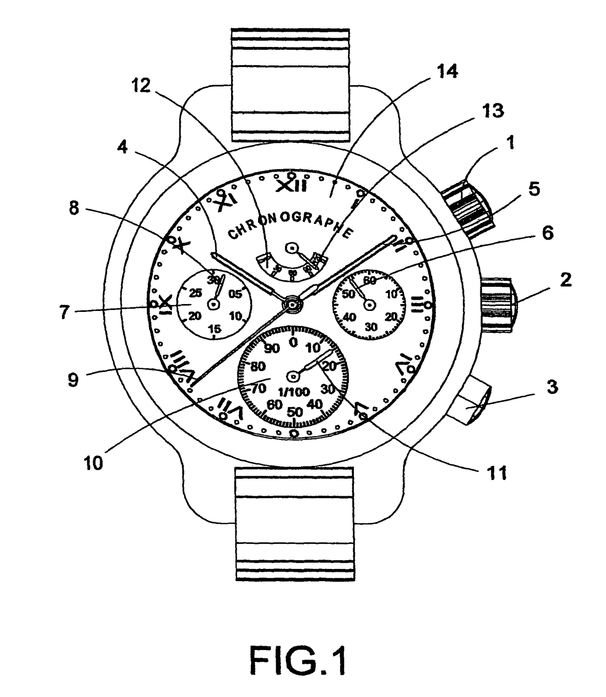
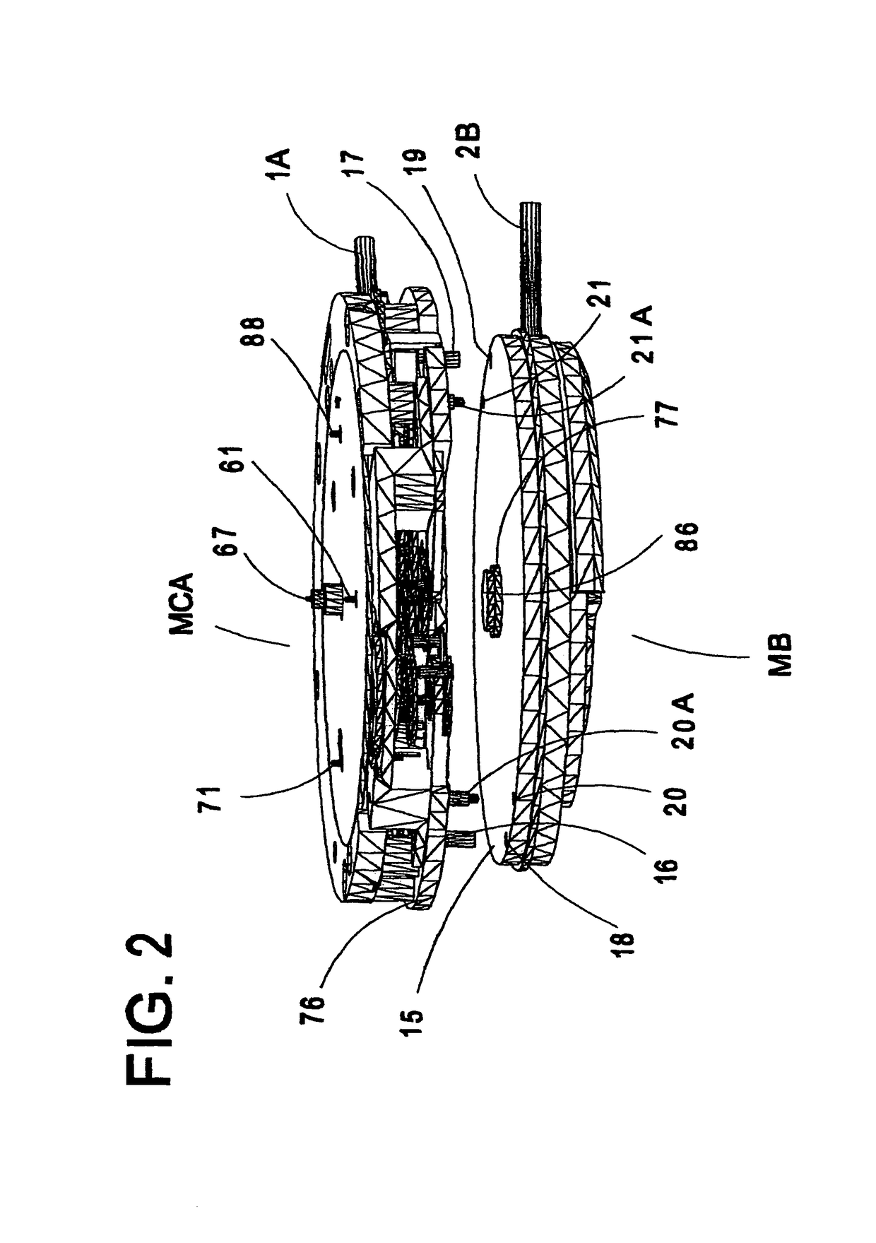
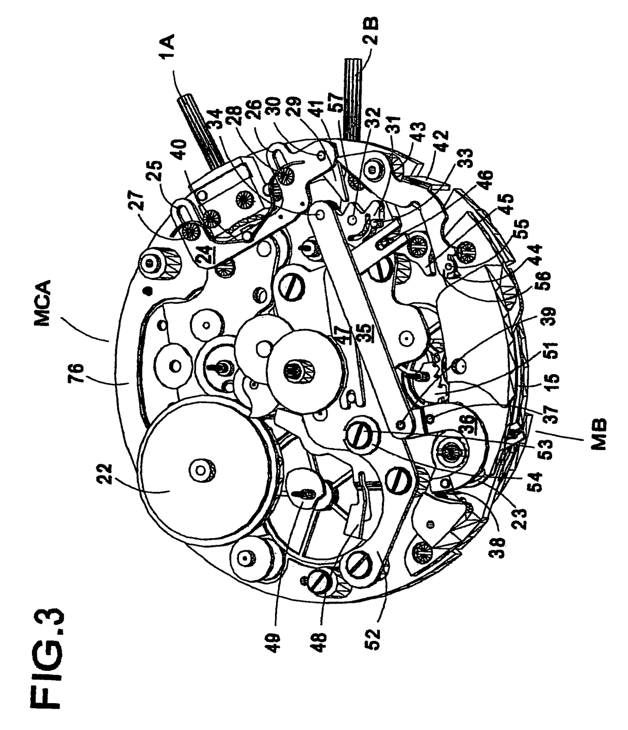
[0025]The device according to the invention will be applied advantageously in a chronograph wrist-watch (not specifically referenced), as represented in FIG. 1. This watch shows: at two o'clock, a push-piece winding-button (crown) 1 for winding a barrel of the device's chronograph module—hereafter called autonomous chronograph module MCA—and for commanding the starting and stopping functions of the autonomous chronograph module MCA, at three o'clock, a winding-button (crown) 2 of the device's clock movement—hereafter called base movement MB—and at 4 o'clock, a push-piece 3 actuated for the resetting to zero and for the flight returning of the autonomous chronograph module MCA. In a preferred embodiment illustrated further below in relation to FIG. 9, the watch comprises a single winding-crown allowing to simultaneously reset and rewind, in different axial positions, the base movement MB and the auxiliary chronograph module MCA.

[0026]The chronograph watch enables the displaying of th...


PUM


Abstract

A device comprises a basic clock movement MB whose time indicators are driven by a first barrel connected to a first wheelwork and a first regulator organ, and an autonomous chronograph module MCA whose indicators are driven by a second barrel independent from the first, connected to a second wheelwork and a second regulator organ. The chronograph module is exclusively composed of mechanical elements. The frequency of oscillation supplied by its regulator is equal N times the frequency of oscillation supplied by the regulator of the base movement, with the coefficient N being definable according to a specific application of the chronograph, so that any chronograph module thus previously defined can work with the same base movement. The chronograph regulator remains constantly engaged with the corresponding wheelwork. The chronograph module allows a time interval to be read with a minimum precision of a hundredth of second. The organs of the base movement and of the chronograph module are arranged in such a way that in assembled state, the height and overall diameter do not exceed 7.75 mm and 30 mm respectively, the dimensions of the chronograph itself being not greater than 4 mm (height) and 30 mm (diameter) when its elements are mounted on a bottom plate, so that the device can advantageously be integrated in the case of a wrist-watch and affords an aesthetic exterior.

Description

REFERENCE DATA[0001]This application is a continuation of international PCT application PCT / CH03 / 00063 (WO03 / 065130) filed on Jan. 27, 2003, claiming priority of European patent application EP02405063.5 filed on Feb. 1, 2002, the contents whereof are hereby incorporated.FIELD OF THE INVENTION[0002]The present invention concerns a device comprising a usual clock movement and a chronograph module according to the preamble of the independent claim 1.DESCRIPTION OF RELATED ART[0003]The market of chronograph watches equipped with a device of this kind has developed considerably during the past years, in particular in the up-market segment. However, a very large proportion of such watches comprise a chronograph plate (hereafter called indifferently chronograph part, module or movement) having a quartz oscillator, whilst a certain clientele feels increasingly attracted to mechanical chronograph watches. With the latter, however, and for reasons that will be explained below, the one skilled...

Claims


Application Information

Patent Timeline
Patent Type & Authority Patents(United States)
IPC IPC(8): G04F7/00G04B1/20G04B27/02G04B27/00G04B1/12G04B9/00G04B37/00G04B37/06G04F7/08
CPCG04B1/12G04B37/066G04F7/0895G04F7/088G04F7/0885G04F7/0809
Inventor JOLIDON, HUGUES
Owner LVMH SWISS MFG SA
Learn More