Ground sleeve having improved impedance control and high frequency performance

a ground sleeve and impedance control technology, applied in the field of ground sleeve, can solve the problem of disturbing the geometrie of the transmission line, and achieve the effect of reducing crosstalk

Active Publication Date: 2011-03-15
AMPHENOL CORP
View PDF15 Cites 144 Cited by
  • Summary
  • Abstract
  • Description
  • Claims
  • Application Information

AI Technical Summary

Problems solved by technology

However, in order to terminate the signal and ground wires of the cable to a connector or electrical element, the geometry of the transmission line must be disturbed in the termination region i.e., in the area where the cables terminate and connect to a connector or electrical element.

Method used


Image

  • Ground sleeve having improved impedance control and high frequency performance
  • Ground sleeve having improved impedance control and high frequency performance
  • Ground sleeve having improved impedance control and high frequency performance

Examples


Embodiment Construction

[0020]In describing a preferred embodiment of the invention illustrated in the drawings, specific terminology will be resorted to for the sake of clarity. However, the invention is not intended to be limited to the specific terms so selected, and it is to be understood that each specific term includes all technical equivalents that operate in similar manner to accomplish a similar purpose.

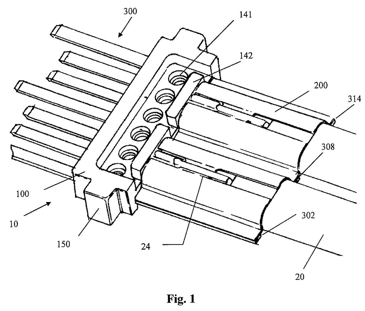
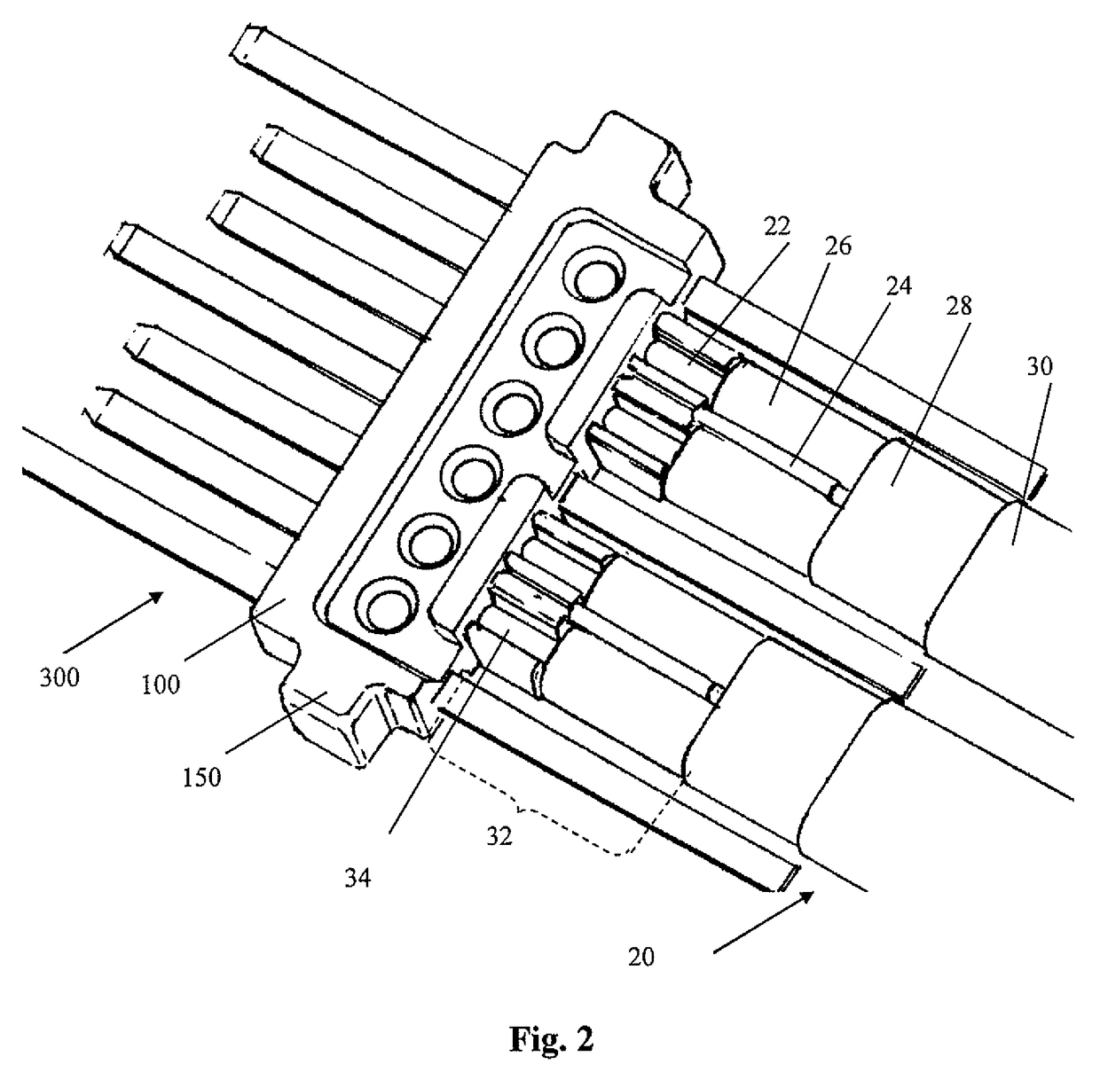
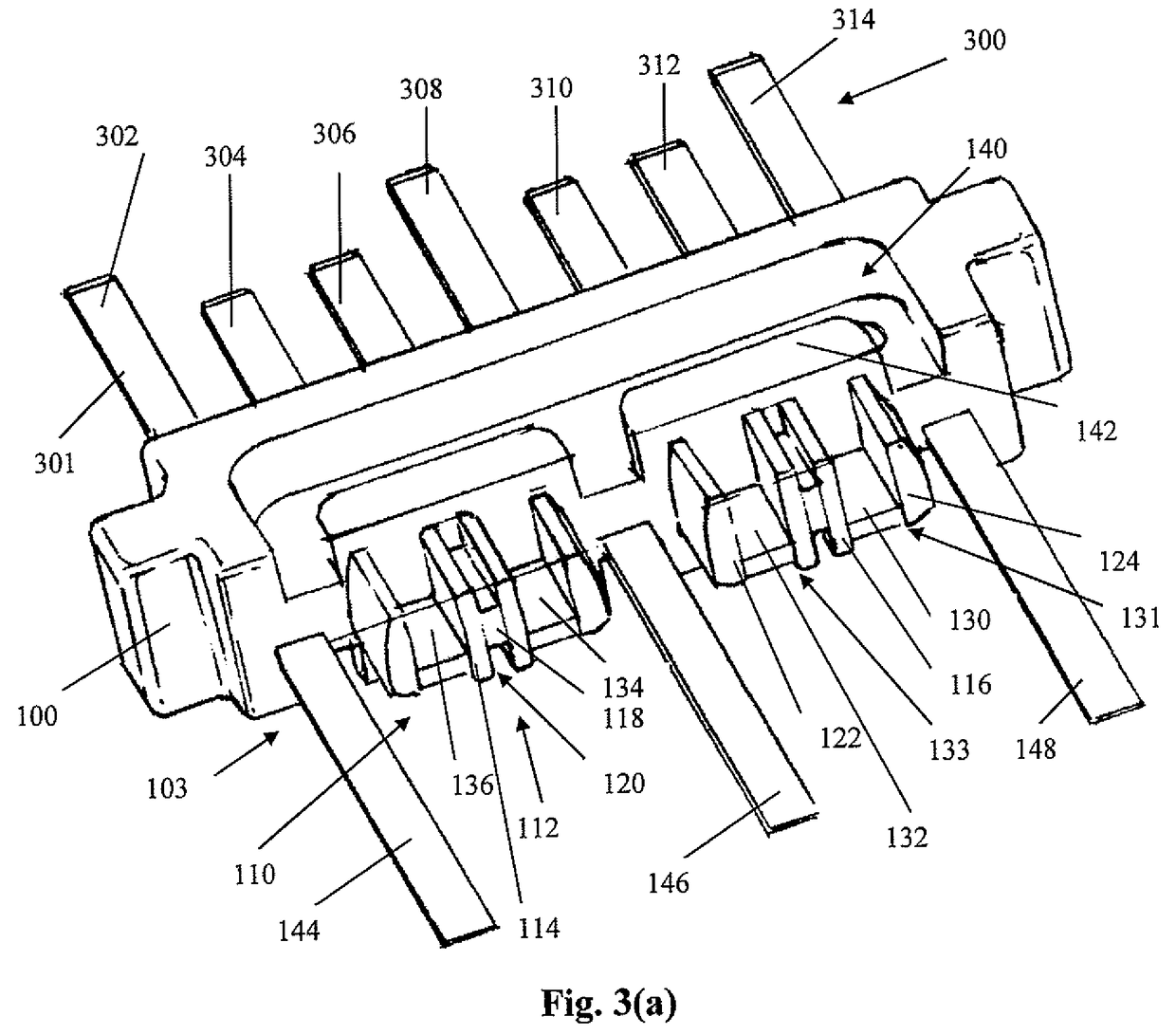
[0021]Turning to the drawings, FIG. 1 shows a connector wafer 10 of the present invention to form a termination assembly used with cables 20. The connector 10 includes a plastic insert molded lead frame 100, ground sleeve 200, and pins 300. The lead frame 100 retains the pins 300 and receives each of the cables 20 to connect the cables 20 with the respective termination land regions 130, 132, 134, 136 (FIG. 3(a)). The ground sleeve 200 fits over the cables 20 to control the impedance in the termination area of the cables 20. The ground sleeve 200 also shields the cables 20 to reduce crosstalk betwe...


PUM


Abstract

A waferized connector connects to two twinax cables. The connector includes a molded lead frame, ground sleeve, twinax cable, and overmolded strain relief. The lead frame is molded to retain a lead frame containing both differential signal pins and ground pins. Termination sections are provided at the rear of the lead frame to terminate each of the signal wires of the cables to respective signal lands. The ground sleeve has two general H-shape structures connected together by a center cross-support member. Each of the H-shaped structures having curved legs, each of which fits over the signal wires of one of the twinax cables. The wings of the ground sleeve are terminated to the ground lands of the lead frame and the drain wire of the cable is terminated to the ground sleeve to terminate the drain wire to a ground reference. The ground sleeve controls the impedance in the termination area of the cables, where the twinax foil is removed to expose the wires for termination to the lands. The ground sleeve also shields the cables to reduce crosstalk between themselves and adjacent wafers when arranged in a connector housing. A conductive slab member is formed over the sleeve to provide a capacitive coupling with the conductive foil of the signal cable.

Description

BACKGROUND OF THE INVENTION[0001]1. Field of the Invention[0002]The present invention relates to a ground sleeve. More particularly, the present invention is for a reference ground sleeve that controls impedance at the termination area of wires in a twinax cable assembly and provides a signal return path.[0003]2. Background of the Related Art[0004]Electrical cables are used to transmit signals between electrical components and are often terminated to electrical connectors. One type of cable, which is referred to as a twinax cable, provides a balanced pair of signal wires within a conforming shield. A differential signal is transmitted between the two signal wires, and the uniform cross-section provides for a transmission line of controlled impedance. The twinax cable is shielded and “balanced” (i.e., “symmetric”) to permit the differential signal to pass through. The twinax cable can also have a drain wire, which forms a ground reference in conjunction with the twinax foil or braid....

Claims


Application Information

Patent Timeline
Patent Type & Authority Patents(United States)
IPC IPC(8): H02G15/02
CPCH01R13/6474H01R13/6464H01R13/6592H01R9/034H01R13/405H01R13/6471H01R13/65914
Inventor ATKINSON, PRESCOTTGEORGE, JOSEPHMILBRAND, JR., DONALD W.
Owner AMPHENOL CORP
Why Eureka
Try Eureka