Device for temperature conditioning an air supply

a technology for air supply and temperature control, which is applied in the direction of sofas, heating types, lighting and heating apparatus, etc., can solve the problems of limiting the acceptance by consumers and affecting the usability and acceptance of air temperature controllable materials

Inactive Publication Date: 2011-03-22
MORPHY RICHARDS LTD
View PDF17 Cites 54 Cited by
  • Summary
  • Abstract
  • Description
  • Claims
  • Application Information

AI Technical Summary

Benefits of technology

[0056]Preferably said casing comprises an elongate tube like structure, having a plurality of air inlets and outlets on a first side, and having a second side which is continuous and devoid of any air inlet / outlet grills, upon which the device may be stood on a floor. This may enable the device to be placed in a plurality of orientations and allow flexibility in positioning the device adjacent a bed.

Problems solved by technology

However, the usability and acceptance by consumers of air temperature controllable materials has been held back by the size, weight, noise and inconvenience of air heating and cooling devices for use with temperature controllable fabrics.

Method used


Image

  • Device for temperature conditioning an air supply
  • Device for temperature conditioning an air supply
  • Device for temperature conditioning an air supply

Examples


second embodiment

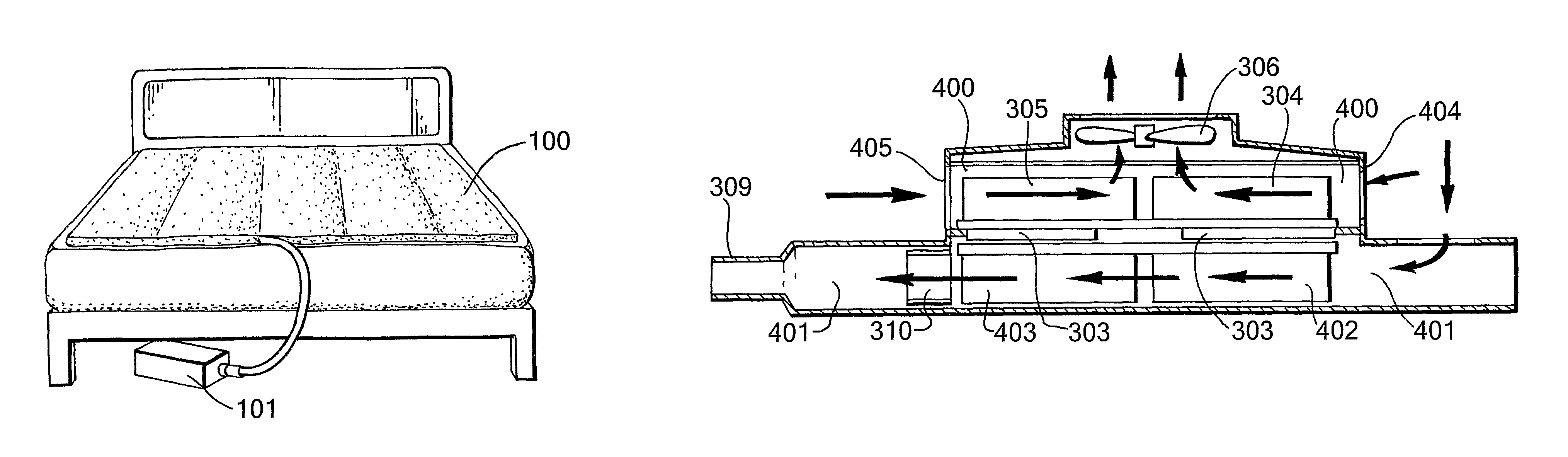
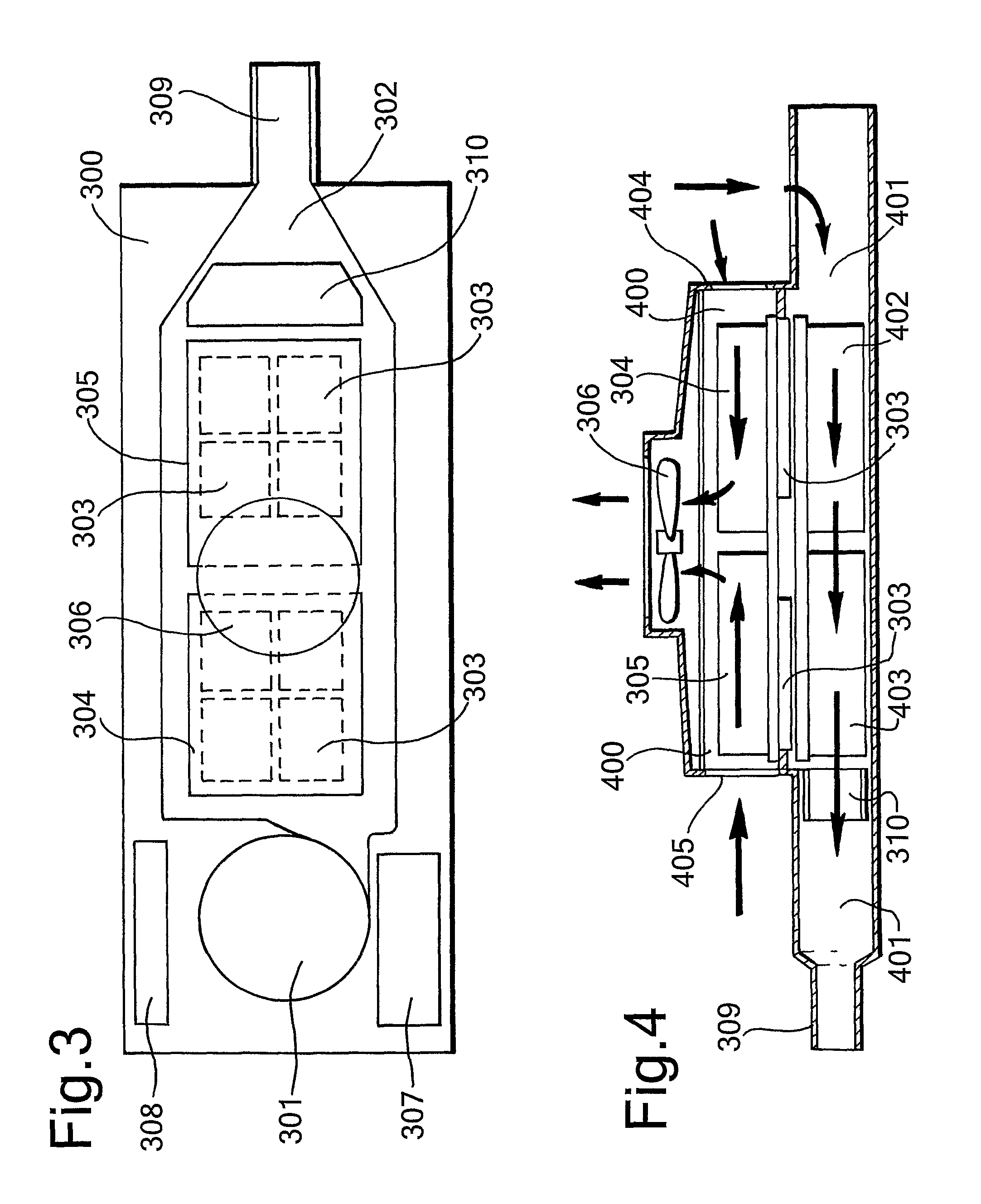
[0130]A second embodiment heating and cooling device comprises a base plate 500 onto which is mounted a tubular structure 501 forming an air conditioning air channel, and an upper tubular structure 502 forming an exhaust channel. The air conditioning channel 501 comprises a substantially rectangular cross sectional tubular passage having at an inlet end a tapered inlet 503 and an outlet end, a tapered outlet portion 504. Within the air conditioning channel are positioned one or a plurality of cast aluminum heat sink devices 504, 505, through which the air is forced by inlet fan 506. Inlet fan 506 is placed with its main axis of rotation substantially perpendicular to a main plane of the base plate 500, so as to draw air in from a direction transverse to the main plane of the base plate. Air therefore passes through 90 degrees through the fan to be expelled in a transverse direction along a main length of the air conditioning passageway 501. The ceramic heating device 506 is position...

fourth embodiment

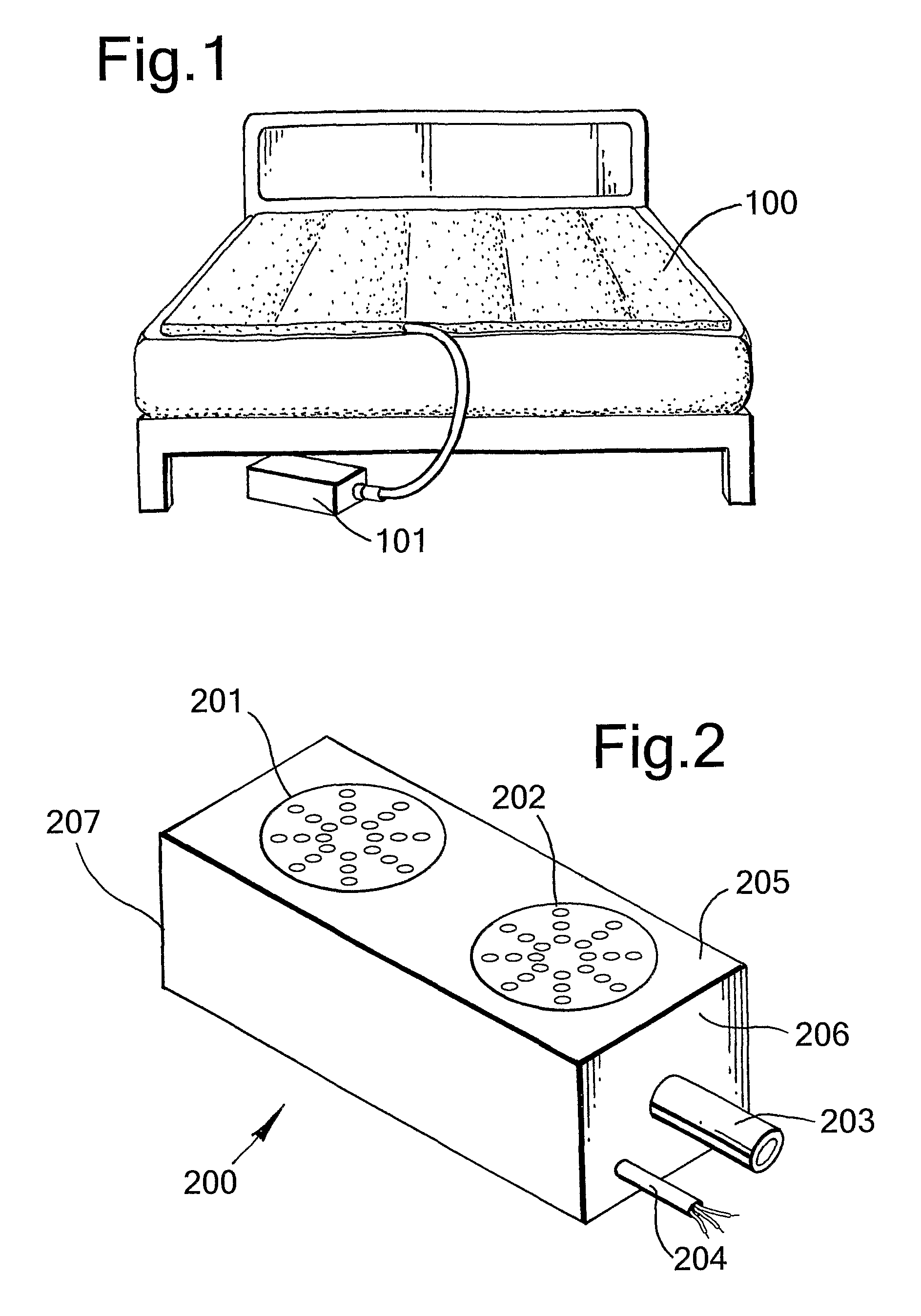
[0186]The fourth air heating and cooling device comprises a double unit, capable of providing conditioned air to two air mattresses via two heat conditioning modules in a single device. The device effectively two single air heating and cooling devices placed side by side in a single casing 2200. In FIG. 22, the front of the casing is removed to show internal components. The fourth embodiment heating and cooling device relies on an external power supply, in a separate casing, which may be connected to the fourth heating and cooling device via an electrical cable 2201 which enters the rear of the casing, at a position approximately mid way along the length of the casing.

[0187]Each individual air heating and cooling device within the casing comprises a primary heat exchanger axial fan for drawing air through a heat sink device 2203 in an air conditioned air channel; a heat exchanger device comprising a first heat sink 2203 and a second heat sink, the first and second heat sinks being s...


PUM


Abstract

A heating and cooling device for temperature conditioning an air supply for an air conditioned appliance, said heating / cooling device comprising: a first air passage for channeling a first air flow; a second air passage for channeling a second air flow; an inlet fan for drawing air into said first, air passage; an exhaust fan for drawing air through said second air passage; one or a plurality of heat exchangers for exchanging heat between air in said first air passage and air in said second exhaust air passage; wherein said first air passage comprises a tubular channel having an inlet at a first end and only one outlet, said outlet being at a second end of said passage, and said inlet fan is positioned at said inlet, such that said first air flow is channeled through said inlet fan, along the whole of said air passage, encountering all of said one or plurality of heat exchangers, and out of said outlet.

Description

CROSS-REFERENCE TO RELATED APPLICATIONS[0001]This application is a 371 U.S. National Stage of International Application No. PCT / GB2007 / 000502, filed Feb. 15, 2007. This application claims the benefit of British Patent Application No GB 0603292.4, filed Feb. 17, 2006. The disclosures of the above applications are incorporated herein by reference.FIELD OF THE INVENTION[0002]The present invention relates to a device for temperature conditioning an air supply, particularly although not exclusively, to an air mattress device.BACKGROUND TO THE INVENTION[0003]It is known to provide flexible webs of material having a plurality of tubular channels through which air can flow, so that heated or cooled air can pass along the air channels to provide a warmed or cooled pad of material. Such materials can be used in temperature controlled garments, temperature controlled seats for automotive use, and temperature controlled blankets or mattresses.[0004]Typically, such temperature controllable mater...

Claims


Application Information

Patent Timeline
Patent Type & Authority Patents(United States)
IPC IPC(8): A47C21/04
CPCA47C21/044A47C21/048F24F5/0042A47C21/04F24F3/001F24F5/0096F24H3/0417F24H3/12F25B21/04
Inventor WARD, BARRYBARKER, DAVID
Owner MORPHY RICHARDS LTD
Why Eureka
Try Eureka