Recoil mechanism and device

a recoil mechanism and recoil technology, applied in the field of non-motorized recoil devices, can solve the problems of pulling line to jump off, becoming fouled and tangled, and achieve the effects of preventing corrosion, reducing friction, and reducing friction

Inactive Publication Date: 2011-03-22
KNOTTY DUCK DECOYS
View PDF56 Cites 6 Cited by
  • Summary
  • Abstract
  • Description
  • Claims
  • Application Information

AI Technical Summary

Benefits of technology

[0012]Additional features of the present invention include an elastic drive member that is well-suited for field repair combined with a design for attaching the drive member to a rotatable shaft. Elastic drive member includes known materials including, but not limited to, natural or synthetic rubber, latex, or other suitable combinations of material. The rotatable shaft includes a pair of slots adapted to slideably receive a respective knotted end of the elastic drive member. Further, the large surface area of the spindle ensures that the pull cord easily winds around the spindle and prevents jams common in the prior art.
[0013]Other key features of preferred embodiments of the present invention include hardware fabricated from stainless steel or 6061 Aluminum. One possible bushing material includes an oillette self-lubricating bronze bushing. Preferably, the various components consist of stainless steel or Aluminum to provide durability and prevent corrosion for years of use and serviceability with limited maintenance. Accordingly, a preferred embodiment constructed with such materials requires minimal maintenance comprising simply to clean and rinse the components with salt-fee water after use in saltwater environments. No oil or grease-filled bears are used and, therefore, the rotating components will not gum up or slow down in cold weather. There is no center pulley wheel for the pull line to jump off and become fouled and tangled. All parts are machined within about 0.010-inch tolerances. The front, middle and rear posts have precise holes positioned to allow forward facing or rear facing operation. The rear post also has a machined grove that goes around the post to provide a smooth slot for the drive band to rest in.
[0023]a circumferencially arranged u-shaped channel adapted to help retain the elastic drive member.

Problems solved by technology

There is no center pulley wheel for the pull line to jump off and become fouled and tangled.

Method used


Image

  • Recoil mechanism and device
  • Recoil mechanism and device
  • Recoil mechanism and device

Examples


Embodiment Construction

[0029]Possible preferred embodiments will now be described with reference to the drawings and those skilled in the art will understand that alternative configurations and combinations of components may be substituted without subtracting from the invention. Also, in some figures certain components are omitted to more clearly illustrate the invention.

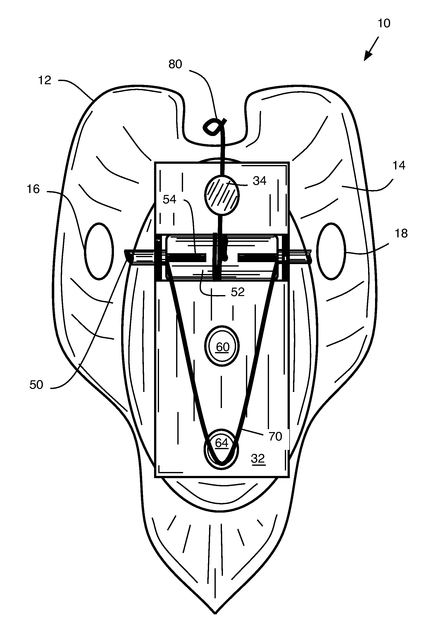
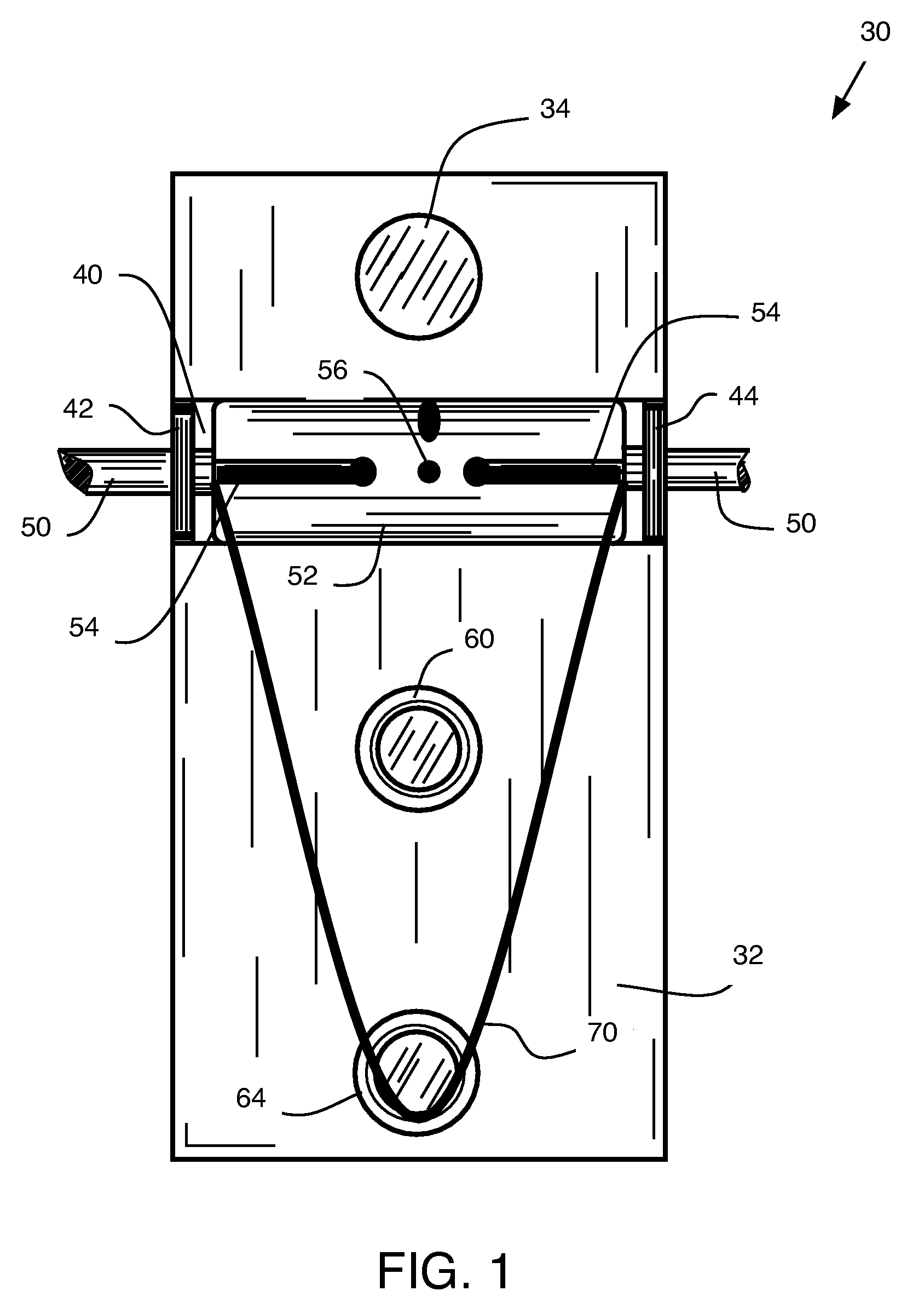
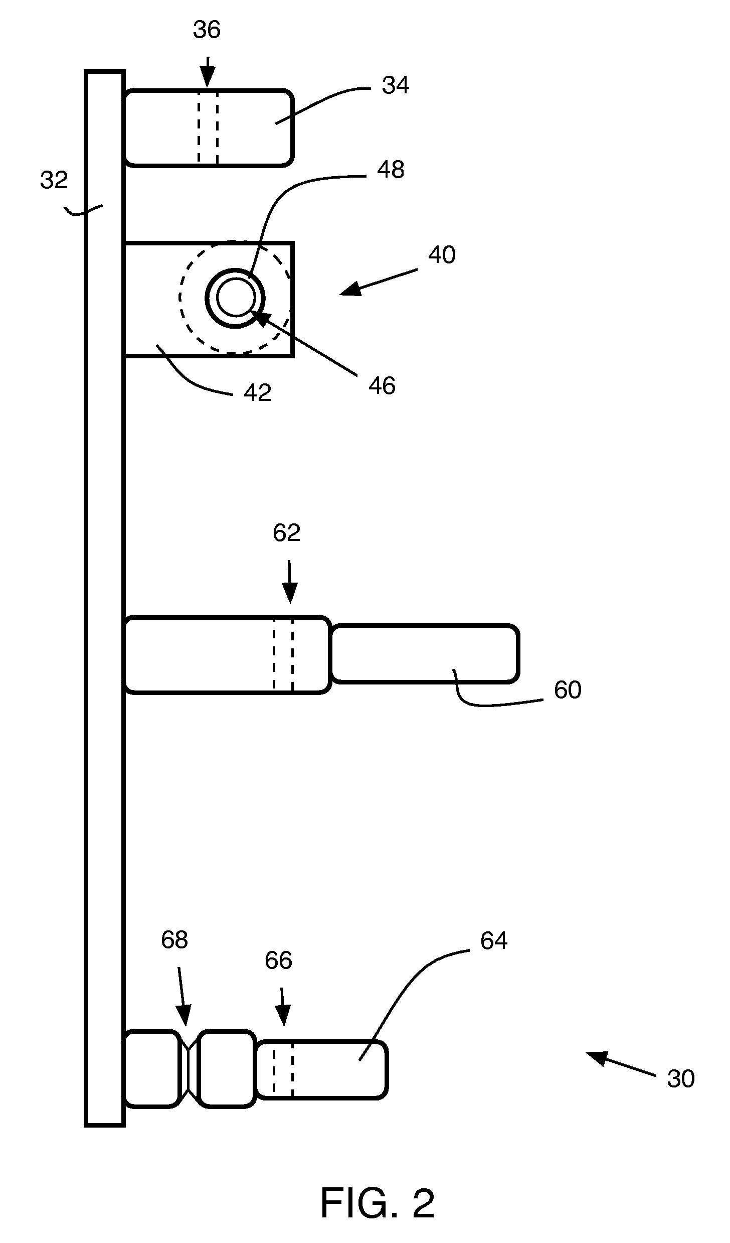
[0030]FIGS. 1 and 2 illustrate a first preferred embodiment of the present invention. The present invention comprises a non-motorized recoil mechanism 30 adapted for waterfowl decoys. Accordingly a flat plate member 32 adapts to couple to a standard or customized waterfowl body shell as would be understood in the art. One particularly well-suited plate member includes a generally flat piece of aluminum alloy measuring approximately 10-inches by about 3-inches and having a thickness of about ⅛-inch, which corresponds to a common bar stock as used in the relevant art. The plate member includes various through holes or other mounting feature...


PUM


Abstract

A non-motorized waterfowl decoy device includes a recoil mechanism adapted for use in a front-facing position or a rear-facing position. The recoil mechanism includes a rotatable spindle having a long axis about four times greater than its diameter. The recoil mechanism further includes a elastic drive member adapted to slidably couple into a pair of corresponding slots on the spindle and engage a rear-support post having a u-shaped alignment channel. A pull cord attached to the spindle causes the spindle to rotate and coil the elastic drive member. Positioning the pull cord through a provided aperture on the rear guide-post enables reward-facing operation and, positioning the pull cord through a provided aperture on a front guide posts enables forward-facing operation.

Description

BACKGROUND[0001]The present invention relates to recoil devices for motion decoys and particularly to a non-motorized recoil device for a waterfowl decoy.[0002]One of the most enduring and legal hunting methods for attracting waterfowl is through the use of a decoy that mimics the appearance of the targeted waterfowl. The use of both live and artificial decoys in the United States by native North Americans for waterfowl hunting is documented back over one-thousand years. However, the practice of using live decoys has been abolished at the federal and state levels since the Migratory Bird Treaty Act of 1918. And the use of artificial decoys has grown ever since.[0003]Early artificial decoys were expertly carved from wood and painstakenly hand painted. Over time motion was added to the artificial decoys. More recently (since the introduction of low-cost materials and manufacturing methods introduced in the 1950's) today's waterfowl hunter uses life-like (in appearance) decoys that emu...

Claims


Application Information

Patent Timeline
Patent Type & Authority Patents(United States)
IPC IPC(8): A01M31/06
CPCA01M31/06
Inventor ALLEN, JONBRONSON, ALAN
Owner KNOTTY DUCK DECOYS
Why Eureka
Try Eureka