Motor

a motor and motor body technology, applied in the field of motors, can solve the problems of increasing the sliding resistance of the rotor, affecting the performance of the motor, so as to prevent the flow of fused resin, and improve the air tightness

Inactive Publication Date: 2006-03-14
MITSUBISHI ELECTRIC CORP
View PDF14 Cites 8 Cited by
  • Summary
  • Abstract
  • Description
  • Claims
  • Application Information

AI Technical Summary

Benefits of technology

[0018]Another motor includes: a core round which a coil is wound through a bobbin and in which a magnetic field is generated by applying an electric current to the coil; a stator formed by integrally molding the coil, bobbin and core; a rotor provided with a magnet; and a boss supporting an end of this rotor and tightly shielding a space between the rotor and the stator from one end side of the rotor. In this motor, both boss and stator are partially provided with irregularities at a part of a contact face between them. As a result, it is possible to improve air-tightness between the boss and the stator.
[0019]Either a sealant or an adhesive is applied to the contact face where both boss and stator are provided with irregularities. As a result, it is possible to further improve the air-tightness.
[0020]A further motor includes: a core round which a coil is wound through a bobbin and in which a magnetic field is generated by applying an electric current to the coil; a stator formed by integrally molding the coil, bobbin and core; a rotor provided with a magnet; and a cover made of a resin that covers tightly an end of the stator by being welded to the end of the stator. In this motor, after disposing a resistance wire in a groove provided on the stator and inserting a protruding part of the cover in this groove, an electric current is applied to the resistance wire, thus, the stator and the cover are welded together. Further, in the motor, a recess is provided around the protruding part of the cover in a direction opposite to the protruding part. As a result, it is possible to prevent any fused resin flowing out of the space between the cover and the stator at the time of welding.
[0021]A still further motor includes: a core round which a coil is wound through a bobbin and in which a magnetic field is generated by applying an electric current to the coil; a stator formed by integrally molding the coil, bobbin and core; a rotor provided with a magnet; and a cover made of a resin that covers tightly one end of the stator by being welded to the end of the stator. In this motor, after disposing a resistance wire in a groove provided on the stator and inserting a protruding part of the cover in this groove, an electric current is applied to the resistance wire, thus the stator and the cover are welded together. Further, in this motor, a protruding part is provided along the resistance wire at a port for leading out and connecting the resistance wire to an outside power supply. As a result, it is possible to improve air-tightness around the resistance wire.
[0022]A yet further motor includes: a brush; a commutator onto which this brush comes in contact and slides; a core round which a coil is wound through a bobbin and in which a magnetic field is generated by applying an electric current from the brush to the coil; a rotor provided with a magnet; and a terminal which is fixed to the bobbin, and to which the coil is soldered; a stator formed by integrally molding the coil, the bobbin, and the core; and a protruding part which is formed by bending from the terminal, and to which the coil is soldered. As a result, it is possible to facilitate the soldering process and prevent the soldering from being shaved off by the mold at the time of molding the stator.
[0023]The protruding part is preferably provided with a cutout part, which makes it easily to wind the coil round the terminal.

Problems solved by technology

Therefore, there is a possibility that powder produced by abrasion at a brush falls on the upper face of the stator, gradually moves inside, and enters from a motor shaft part into the motor (especially into a bearing holding portion of the stator).
This eventually results in increase in sliding resistance of a rotor.
However, the face to which the fluid sealant is applied is flat, and this brings about a disadvantage that a joint gap is formed due to irregular configuration in the flat surface and a minute change in configuration after continuous operation, thereby losing air-tightness.
Such a conventional art, however, has a disadvantage that the resin overflows at the time of welding due to dimensional irregularity in the rough portion to be welded, and leakage (poor air-tightness) occurs in the space between butt parts depending upon the manner the wire is set.
In the case where the terminal and the winding (coil) are joined together by soldering, it is essential to soak the whole terminal in solder, and as a result, the whole terminal is unnecessarily soldered.
This causes a disadvantage that the-solder flows out of a portion molded in a mold at the time of molding the stator core, and the soldering is carried out while shaving off the solder sticking to the terminal.
Consequently, a problem exists in that solder shavings are accumulated in the mold and are mixed with the resin.
As discussed above, in the conventional motor, a problem exists in that powder is produced by abrasion at the brush, and enters into the motor, thereby increasing the sliding resistance of the rotor.
Another problem exists in that a joint gap occurs due to irregular configurations of the flat surface part at the space between the stator portion and the boss portion fitted into the stator portion and to a minute change in configuration after a continuous operation, eventually resulting in losing air-tightness.
A further problem exists in that, at the time of welding the position sensor portion and the stator portion together by hot wire method, the resin overflows due to dimensional irregularity of the welded portion.
Thus, leakage (poor air-tightness) occurs at the gap between butt parts depending upon the manner of setting the wire.
A still further problem exists in that the soldering is carried out while shaving off the solder sticking to the terminal and, as a result, solder shavings are accumulated in the mold and are mixed with the resin.

Method used


Image

  • Motor
  • Motor
  • Motor

Examples


embodiment 1

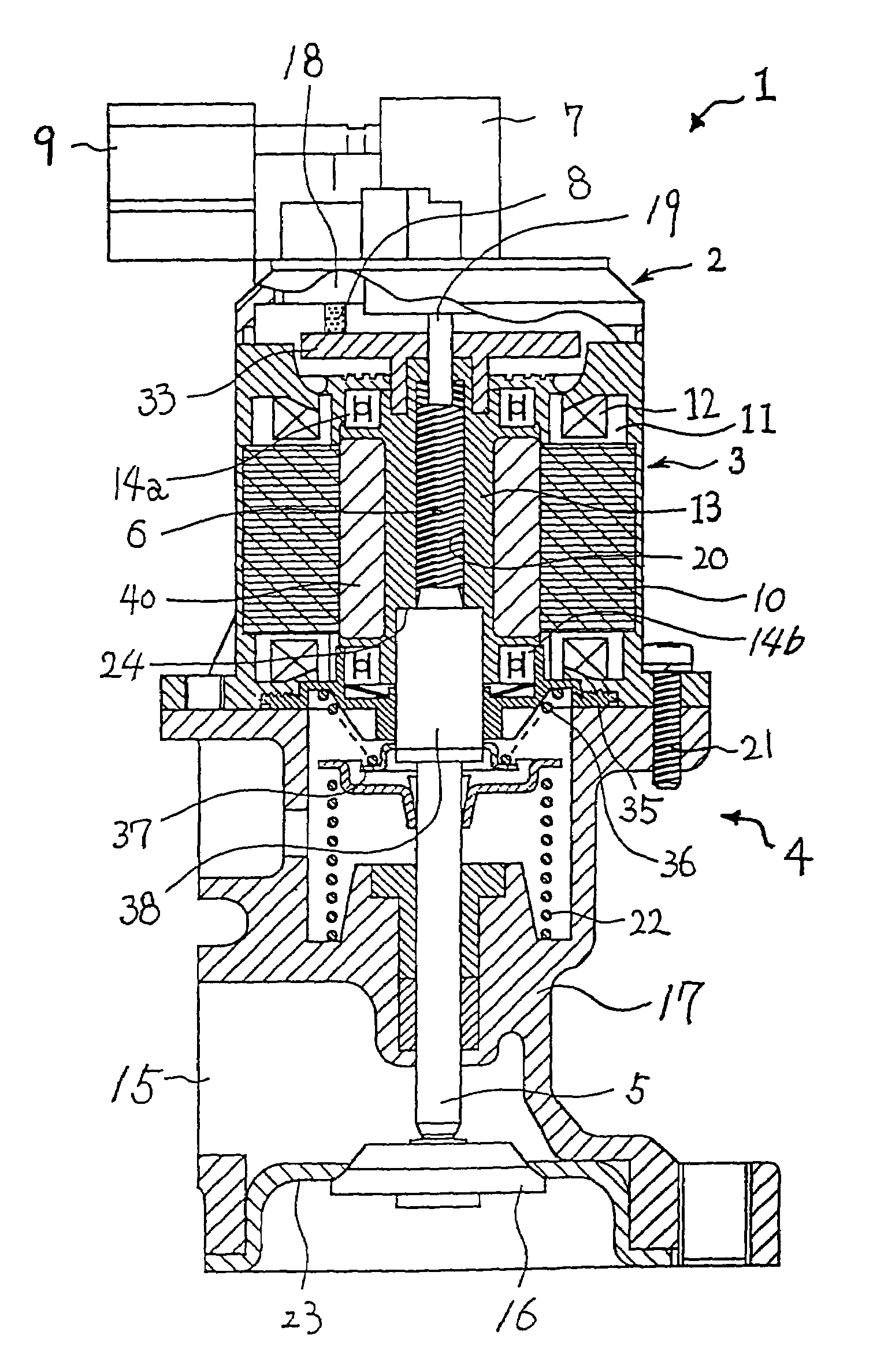
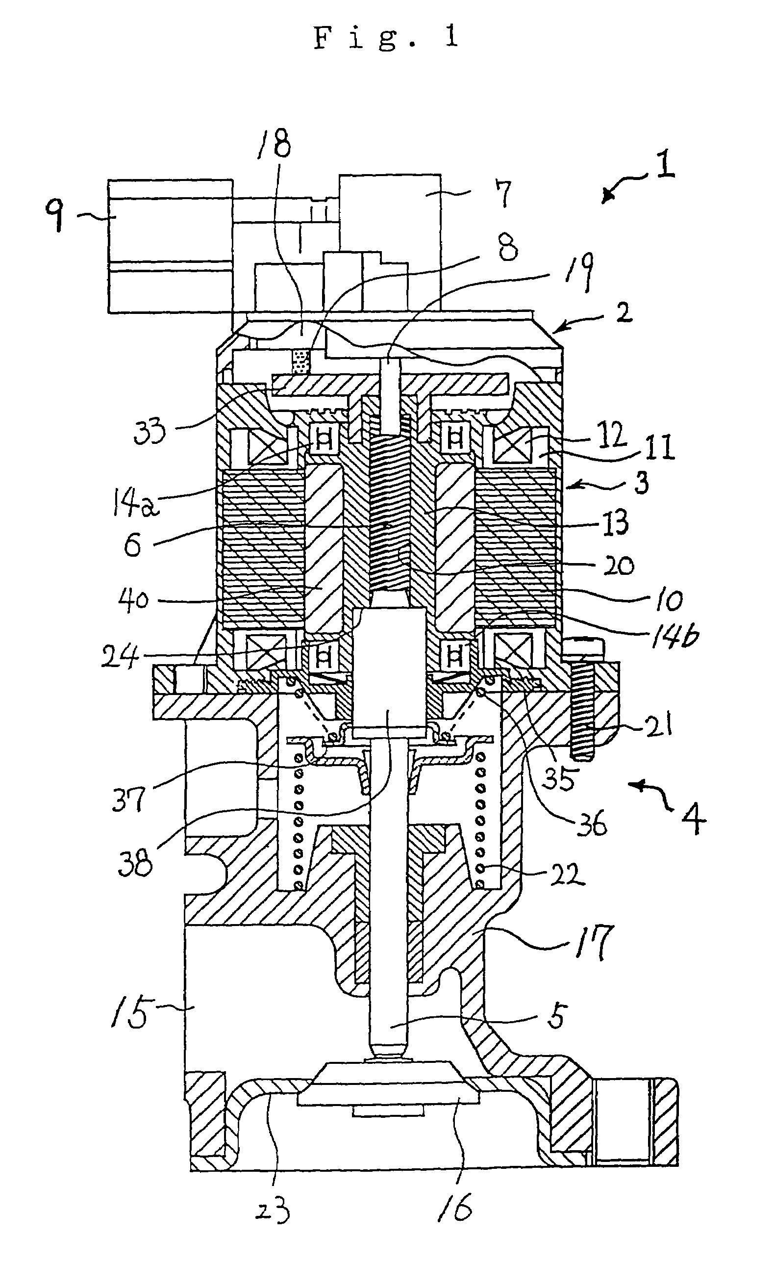
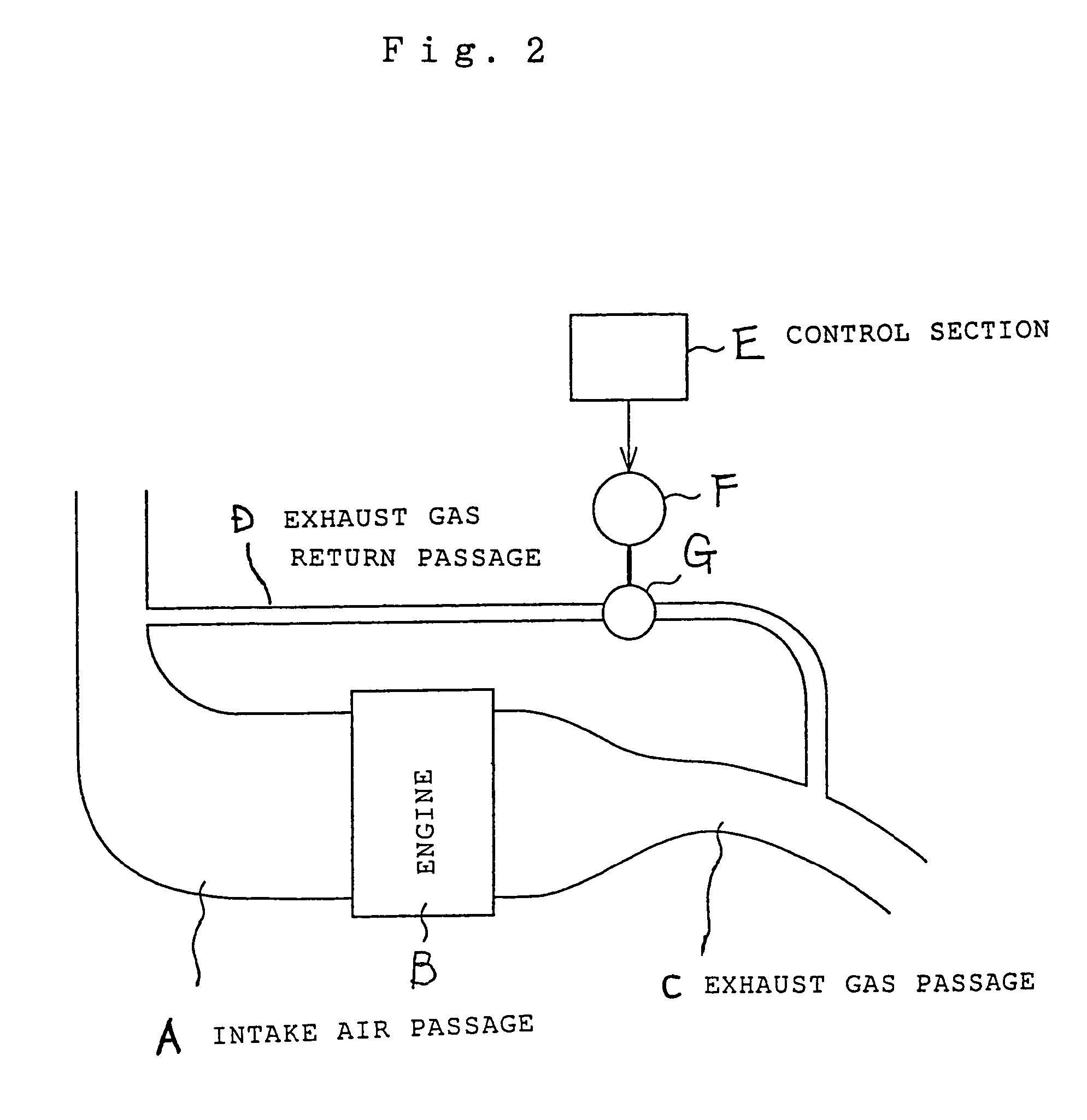
[0049]FIG. 1 is a sectional view of an EGR-V in which a motor according to Embodiment 1 of the present invention is used, and FIG. 2 is an explanatory diagram for explaining an EGR system. FIG. 3 is a partially sectional view of a motor portion of the EGR-V, and FIG. 4 is an external perspective view of the motor portion.

[0050]FIG. 5 is a top view of a stator portion according to Embodiment 1, and FIG. 6 is a sectional view of the mentioned stator portion.

[0051]FIGS. 7, 8, and 9 are sectional views of modifications each showing a configuration of an upper face of the stator portion.

[0052]FIG. 10 is a sectional view showing a structure of fitting a boss to a lower part of the stator.

[0053]FIG. 11 is an explanatory view for explaining how a cover of an energizing part and an outer wall of the stator are welded together, and FIG. 12 is a view for explaining a portion where a wire is led out.

[0054]FIGS. 13 to 17 are perspective views of modifications each showing a protrusion formed at ...


PUM


Abstract

Powder produced by abrasion due to sliding between a brush and a commutator is prevented from moving toward a rotor. A recess is provided between the rotor and a slide face of the brush and the commutator, where powder produced by abrasion at the brush may enter into a motor and increase sliding resistance of the rotor. Thus, there is no such powder produced by abrasion entering into the motor as increasing sliding resistance of the rotor.

Description

TECHNICAL FIELD[0001]The present invention relates to a motor, which is used as direct-current motor for driving a valve of a vehicle-mounted EGR-V (Exhaust Gas Recirculation Valve) or the like.BACKGROUND ART[0002]Motors disclosed in the International Publication Nos. PCT01 / 37402 and PCT01 / 37409 are known as conventional motors, particularly motors used in an EGR-V.[0003]However, in such conventional motors, an upper face of a stator is formed into an approximately flat surface. Therefore, there is a possibility that powder produced by abrasion at a brush falls on the upper face of the stator, gradually moves inside, and enters from a motor shaft part into the motor (especially into a bearing holding portion of the stator). This eventually results in increase in sliding resistance of a rotor.[0004]In order to secure air-tightness in lower part of the stator, any fluid sealant is sandwiched between the stator and the boss at a space formed between the stator portion and a boss portio...

Claims


Application Information

Patent Timeline
Patent Type & Authority Patents(United States)
IPC IPC(8): H02K13/00H02K3/52H02K5/10H02K5/14H02K5/22
CPCH02K3/522H02K5/10H02K5/225H02K5/143H02K13/006
Inventor FUJITA, YOUICHIMIYOSHI, SOTSUOHASEGAWA, SATORUTAKAI, KATSUNORI
Owner MITSUBISHI ELECTRIC CORP
Why Eureka
Try Eureka