
Segmented inner stator and brushless permanent magnet motor with the same

a permanent magnet motor and segmented inner stator technology, applied in the field of motors, can solve the problems of difficult and complicated to secure each segment of the inner stator core together, and the one-tooth segmented configuration is not practicable, and achieves the effects of low material cost, easy winding, and high slot filling

Inactive Publication Date: 2007-12-27
NIDEC MOTOR CORP
View PDF32 Cites 7 Cited by
  • Summary
  • Abstract
  • Description
  • Claims
  • Application Information

AI Technical Summary

Benefits of technology

[0005]In light of the background art discussed above, the technical problem to be solved in the present invention is to provide a one-tooth-segmented configuration of an inner stator that has low material cost, high slot fill, and that is easy to wind.
[0011]In yet a further aspect, each core segment is provided with a projection and a convex cutout on the two side surfaces along the peripheral direction for engaging with the adjacent core segments. These projections and convex cutouts are useful for positioning the core segments when they are assembled and during the assembling itself. They can even prevent the core segments from moving radially towards the outside when the core segments are assembled together.
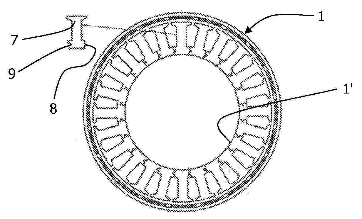
[0014]In still another aspect, the number of the core segments can be equal to that of the stator slots (in one example both are 24) so that the core segments may be wound alone to thereby improve the slot fill.
[0016]The segmented inner stator reduces the consumption of the core material by using a plurality of core segments to form a stator core and thereby to form a segmented inner stator. Meanwhile, the number of the core segments is equal to that of the stator slots, thus the core segments can be wound alone, thereby to improve the slot fill and to be wound more easily.

Problems solved by technology

However, one-tooth segmented configurations are not practically applied to the inner stator configurations because it is difficult and complicated to secure each segment of the inner stator core together.

Method used


Image

  • Segmented inner stator and brushless permanent magnet motor with the same
  • Segmented inner stator and brushless permanent magnet motor with the same
  • Segmented inner stator and brushless permanent magnet motor with the same

Examples


Embodiment Construction

[0027]An exemplary embodiment of a segmented inner stator configuration according to the present invention will be explained with reference to the accompanying drawings, wherein identical parts are represented with identical reference numerals.

[0028]In the present description, the term “circumferential” indicates the peripheral direction of the circular retaining ring (or stator core); the term “axial” indicates the direction along the central line of the retaining ring; and the term “radial” indicates the direction vertical to the central line of the circular retaining ring and through the center of circle of the retaining ring.

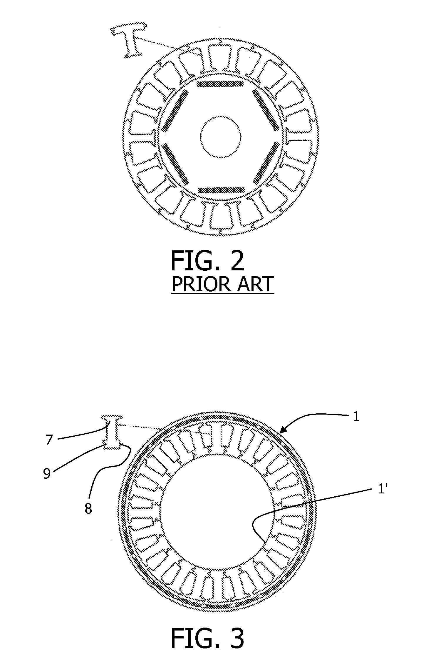
[0029]As shown in FIGS. 3 and 4, a segmented inner stator configuration according to a first embodiment of this invention comprises an inner stator 1 including a stator core 1′, a stator winding, and two circular retaining rings 2, 3.

[0030]As shown in FIG. 7, the stator core 1′ comprises a plurality of generally T-shaped core segments 7. One of the two side ...


PUM


Abstract

A segmented inner stator comprises a stator core and a stator winding. The stator core includes a plurality of core segments which are retained together in a circular arrangement by at least one retaining ring and are mated with each other. At least some of the core segments are provided with slots on the radial side surfaces. The at least one retaining ring comprises a radial extension portion extending along the axial side surface of the core segment. A plurality of corresponding axial projections are provided on the radial extension portion of the at least one retaining ring along the circumferential direction to be inserted into the slot on one of the core segments so that the core segments are not free to move axially and radially relative to each other or relative to the retaining rings.

Description

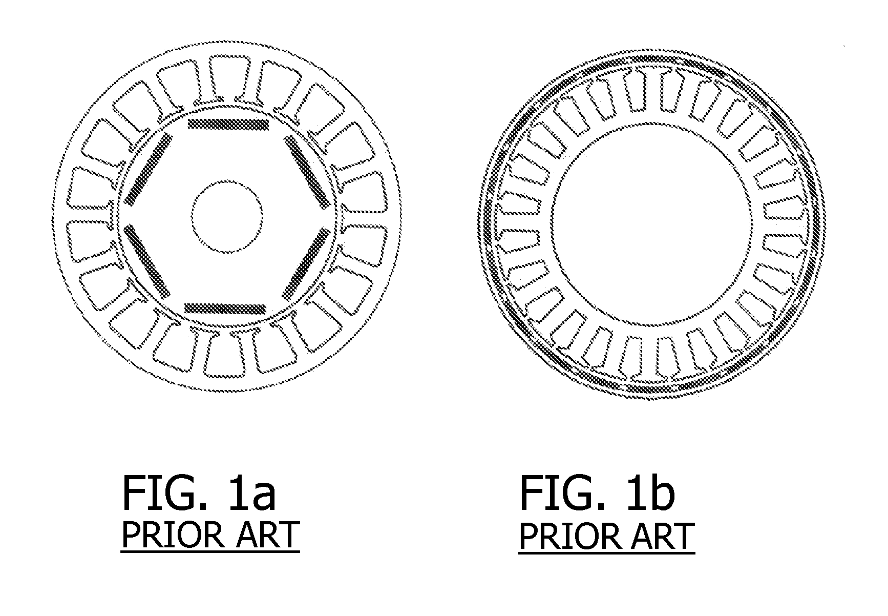
FIELD OF THE INVENTION[0001]The present invention relates to a motor and more particularly, to a segmented inner stator and a brushless permanent magnet motor with the same.BACKGROUND OF THE INVENTION[0002]The use of brushless permanent magnet motors is becoming more prevalent in the motor industry because of their intrinsically high efficiency and low noise. Brushless permanent magnet motors can include either an outer stator configuration (FIG. 1a) or an inner stator configuration (FIG. 1b). In some applications, brushless permanent magnet motors can have a relatively large number of poles, as shown in FIG. 1b. [0003]One-tooth segmented stator configurations are advantageous in that they save core material, increase slot fill, and are easily wound. Currently, however, one-tooth segmented stator configurations are only applied to outer stator configurations (conventional stator), as shown in FIG. 2, because the segmented configuration of the outer stator can be carried out easier t...

Claims


Application Information

Patent Timeline
Patent Type & Authority Applications(United States)
IPC IPC(8): H02K1/28H02K1/12
CPCH02K1/148
Inventor FEI, RENYAN W.XU, YANGUANG
Owner NIDEC MOTOR CORP
Learn More